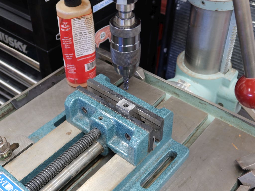
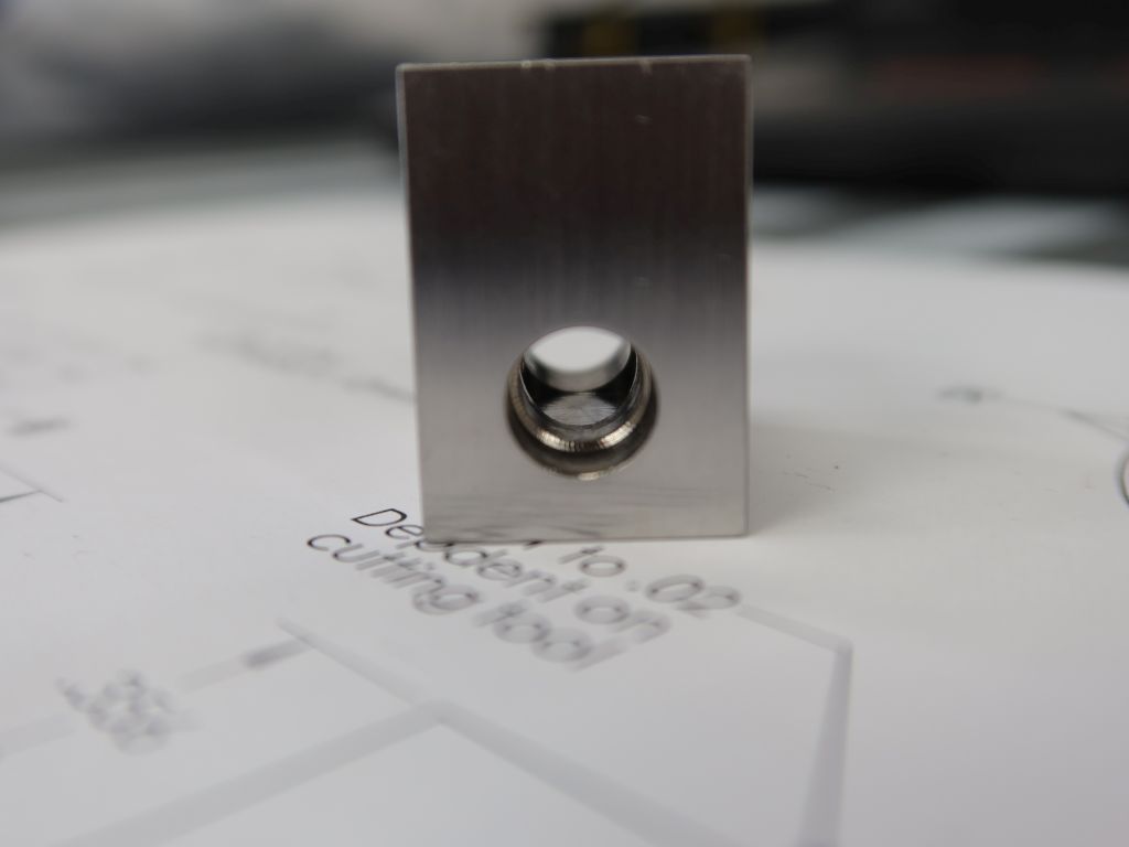
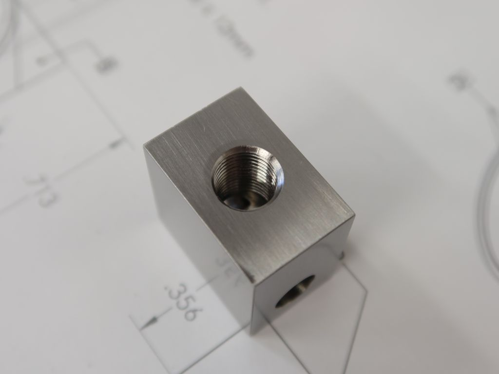
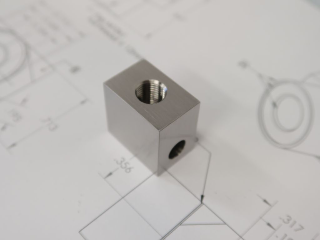
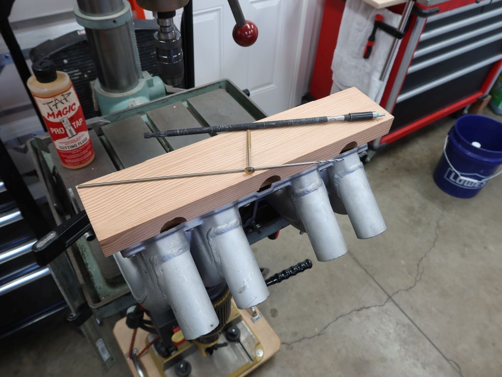
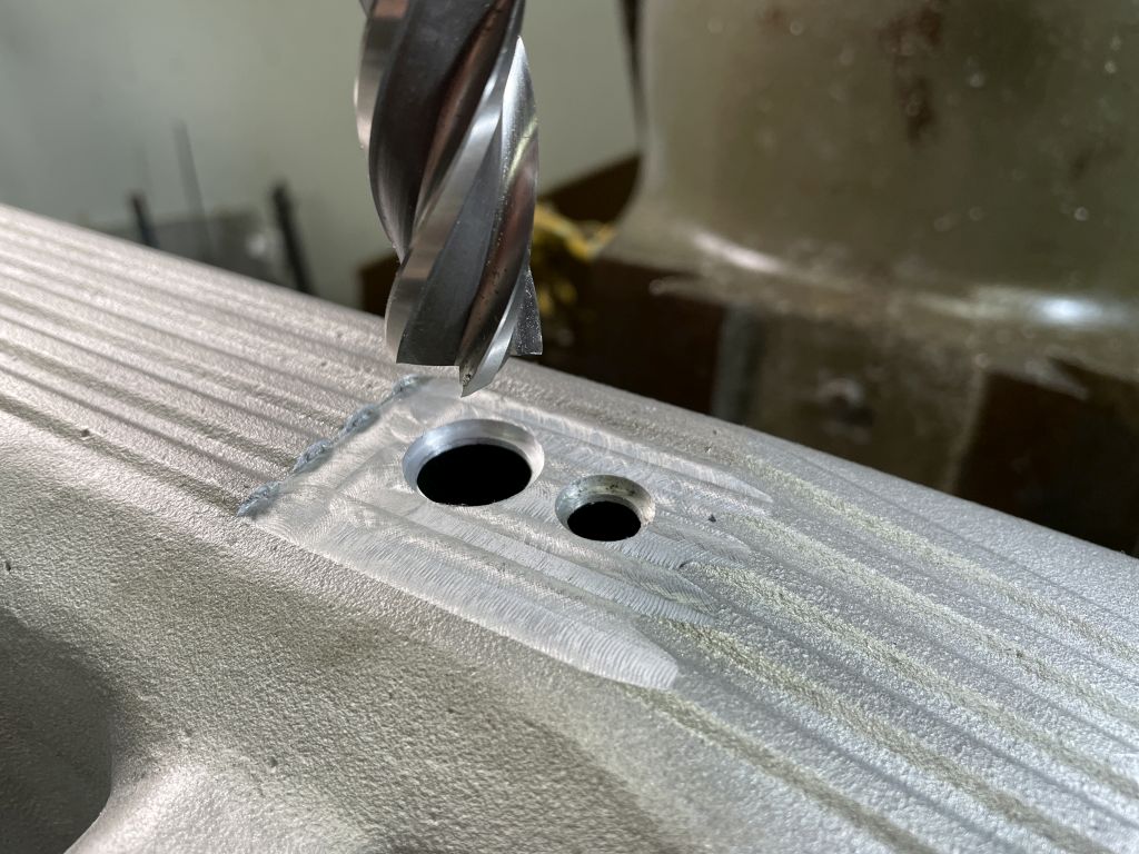
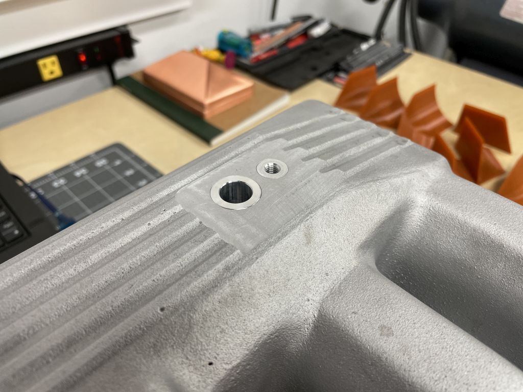
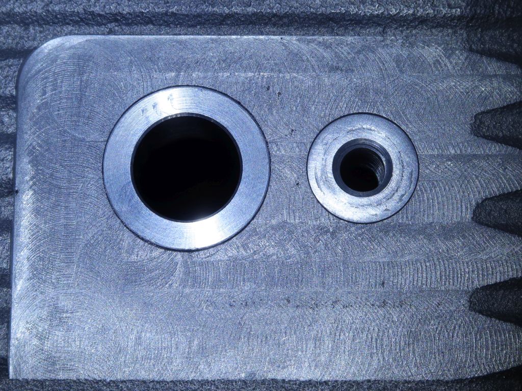
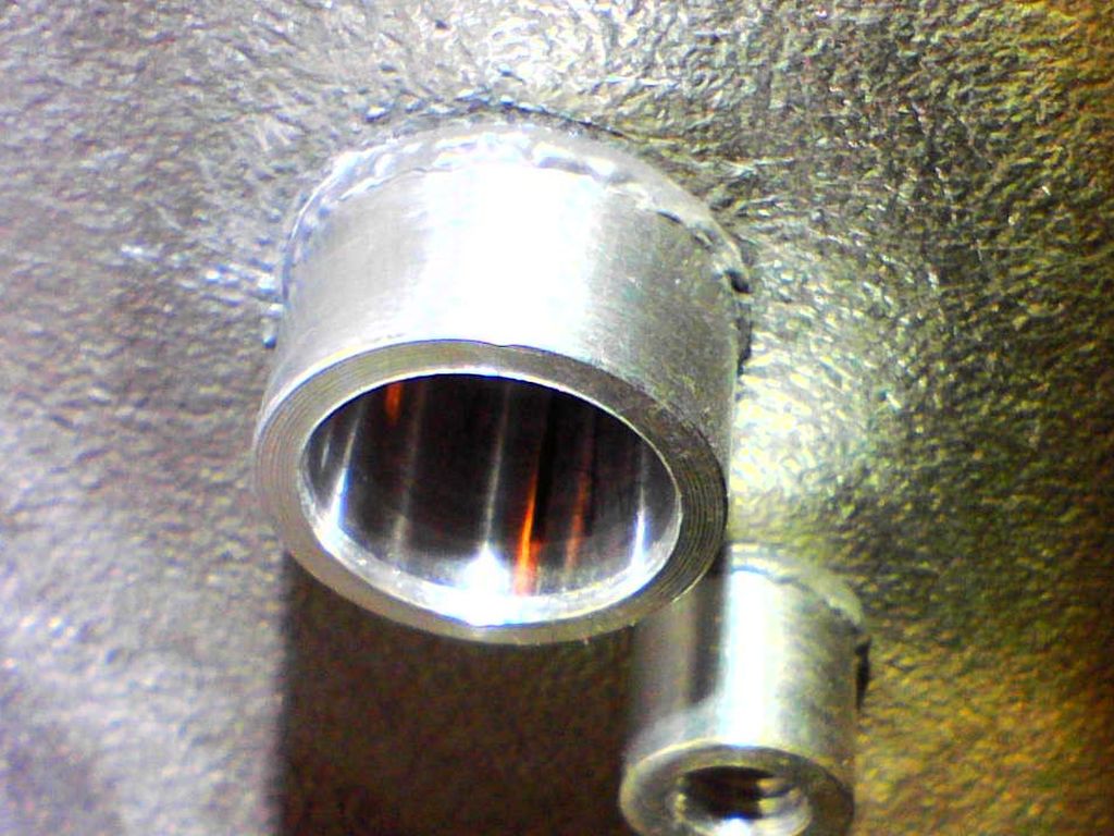
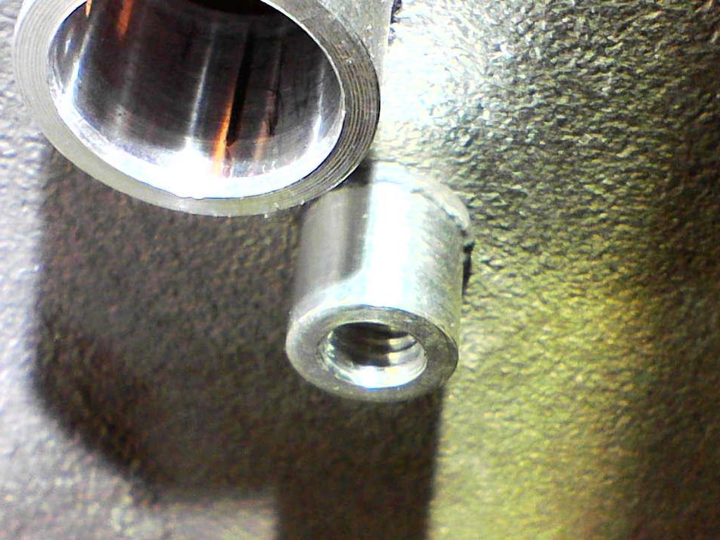
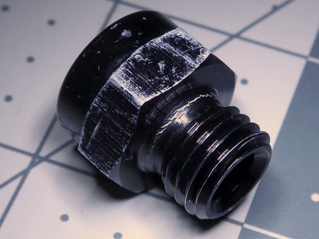
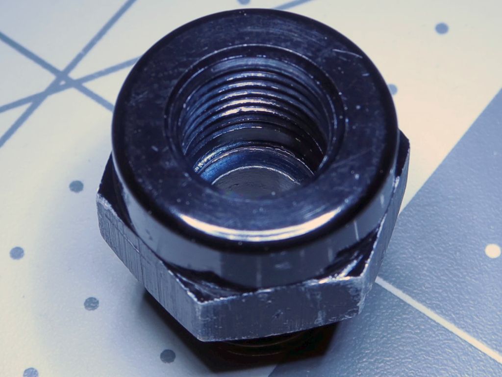
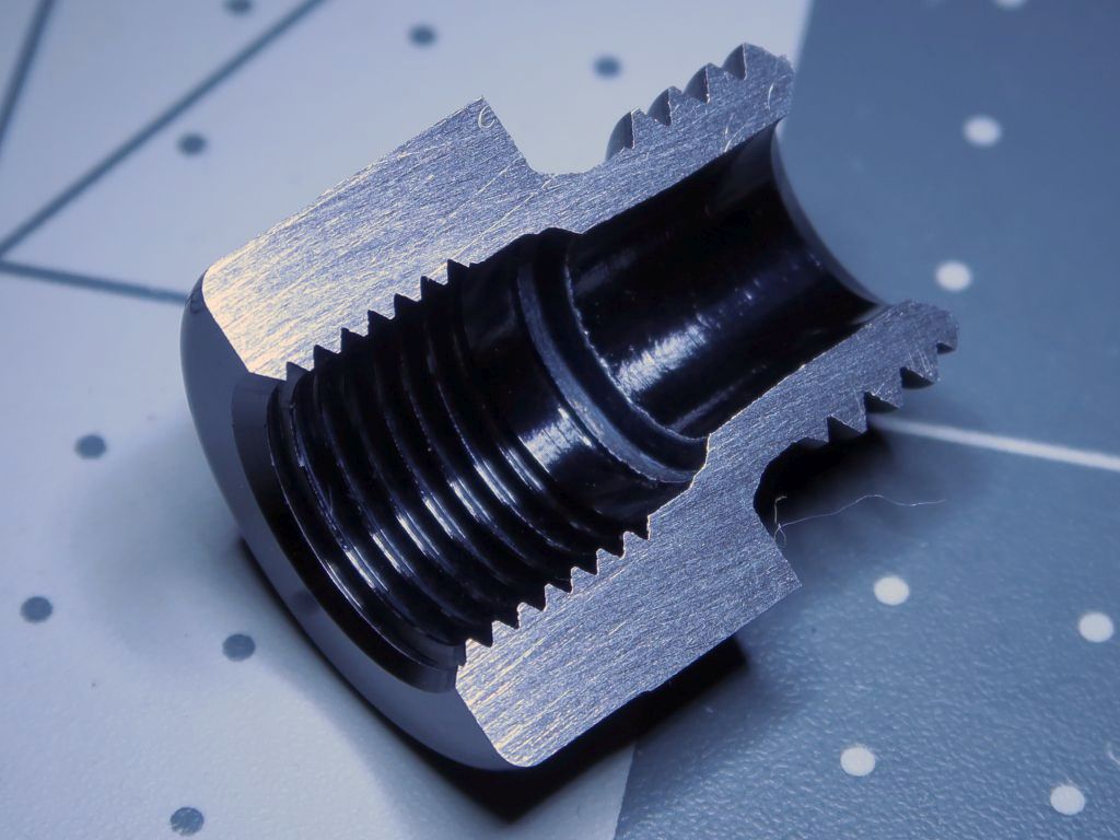
Carbide cutter to the rescue. It made short work of cleaning up the hole that ate my drill bits. It was easy enough to finish this up on the drill press after a little work to make sure that the cutter was centered. The threads cut nice and smoothly.
Announcement
Collapse
No announcement yet.
M42 ECU Conversion: Link G4X / E36X
Collapse
X
-
It has been almost a month since the last update, but I made some solid progress this weekend. All of the part machining tasks are done now! The only remaining fabrication item is to get the stainless fuel feed tube TIG welded to the sensor adapter tee. Once that is done, I can install everything and start trying to make it run. It is hard to believe that I am actually close to that!
One of the two things that needed to happen was to modify the intake manifold to take the Bosch TMap sensor. It was a really simple set of operations, and making the fixture to level the manifold on the mill was more work that actually modifying it.
First, I got the fixture block and manifold lined up as straight as possible so that I could drill the pilot holes for the securing screws. The manifold is a rough cast part, so there really was no perfect flat top to clamp down as a horizontal reference. I eyeballed it as well as I could and then used my digital level to make little adjustments between the wood block and manifold.
I got out my 1/8" x 12" drill bit and a tool bit extension since I was going to need those to get between the runners (especially with the MM pulse chamber thingies in there). I had marked where the manifold bolt holes were with a marker and then drilled. The screw shanks were a few millimeters smaller than the manifold holes, so there was plenty of room for adjustment later.
Here it is test-fitted with some truss-head wood screws.
And of course, no matter how many times I had checked things, I somehow put the holes for mounting to the mill bed in the wrong side lol. Oh well, it is a one-time-use thing.
Here it is after the cuts were all done.
The little adapter sleeves were a nice slip fit. After I clean this thing really well, I am going to epoxy these into place. The larger one is for allowing the TMap sensor's rubber o-ring to seal, and the smaller one has an M6x1 thread for securing it. The top surface of the plenum is ~3mm thick, which is not sufficient for either purpose on its own.
Here's the TMap sensor hanging out in its future home. Well, more like its permanent home. Even if I run the stock ECU I will have a giant vacuum leak without this lol.
The other item that I finished up was the little tee fitting for the fuel temperature & pressure sensor. It came out fairly well with only minimal scuffs and dents (mainly from the vise when I clamped it too tightly for a secondary operation). Once the machining work was done, I went to town on it with a convolute wheel ("Scotch Brite wheel") on the pedestal buffer. It really softened it up. Brushed stainless looks really nice! Too bad this thing is going to be buried down in the engine bay.
As mentioned at the top of the post, I need to get the little fuel tubes TIG welded into place. It should be a simple job. Note that the orientation shown is not the final one...the sensor would not fit if the tubes were welded in that way. It is sort of cramped down where this will go. The sensor will be just to the side of the starter and the largest wire which is hooked up to it, and it will need to point sort of up and forward to clear things.
Comment
-
Phew, big milestone. All fab work is done (as far as I can tell...fingers crossed that I don't find any more lol).
I had a local guy TIG the fuel tee together and it came out looking very good. I have it a quick whack with a fine wire wheel to get it all to a uniform color and installed it. The sensor is installed with 40Nm (30ft-lb) per the datasheet. While I was in there I replaced all of the fuel soft-lines under the hood, and I am going to do the ones at the rear of the car in the near future. other than that, I just need to install the sensor for the oil into the back of the head. For now I am going to put things back together and keep running on stock engine management, probably until closer to Christmas when I will have more of a chunk of time to dedicate to bring-up with the new system.
For now though, here's how the fuel stuff turned out. It almost looks OEM!
- Likes 1
Comment
-
Originally posted by bmwman91 View PostAll fab work is done (as far as I can tell...fingers crossed that I don't find any more lol).
I went to assemble the PST-F1 into the aluminum adapter that I bought, and it did that thing where the wrench keeps turning, but it is not getting tighter. The Bosch datasheet spec's the torque at 40Nm (~30 ft-lb) which is sort of a lot for an M10, but I don't need leaks. The sensor in the previous post torqued down just fine in the stainless fuel line adapter, so I am assuming that the aluminum used in this adapter is some low-grade junk. On top of that, the adapter is really not well designed. The company that makes and sells them says that they are specifically for this sensor, which is primarily intended to seal using the conical surface at the tip of the threaded barrel. Well, you can see what happened. The force from the conical part caused the adapter to start shearing. I am REALLY glad that this failed on the bench when I was applying the specified torque. If I had gotten it to seat, installation into the head would have put even more shear load on the same thin cross section, and I probably would have had a broken adapter stuck in the back of the head.
Just for fun, I cut it in half with a hack saw and sanded it smooth. Yeah...not a great design, and certainly not rated for the application it says it is for. You can see where the sensor started pushing in the aluminum by the step in the inner 45° surface at the bottom of the M10 hole. The initial minimum section thickness through there is ~1.9mm.
Anyway, I made a new one out of some 303 stainless. The same cross section is now ~2.75mm thick, and I am using a copper crush washer so that the sensor is not pre-loading the weakest part of the adapter. I think that this should take care of any issues.
The sensor torqued down just fine, and I used a little blue thread locker for good measure.
Last edited by bmwman91; 11-28-2022, 11:00 AM.
- Likes 1
Comment
-
Dang dude, looking good! You put my harness skills to shame for sure :)
I like what you did with the IAT/MAP sensor. I really dislike the hard line I have for the MAP sensor. A combined sensor like that would work great! I also liked how you milled the flat spot and used inserts for proper sealing!-Nick
M42 on VEMS
Comment
-
Originally posted by wazzu70 View PostDang dude, looking good! You put my harness skills to shame for sure :)
I like what you did with the IAT/MAP sensor. I really dislike the hard line I have for the MAP sensor. A combined sensor like that would work great! I also liked how you milled the flat spot and used inserts for proper sealing!
Once the car is running at peak performance, I will look into an ITB conversion lol. You know, you can't just let a car run well and drive it...gotta always be breaking stuff!
- Likes 1
Comment
-
Very well documented, I like seeing these no-detail-spared conversions come up from time to time. You probably couldn't ask for a better starting platform to learn tuning than a low-strung NA job like your M42. I know it's not stock, but short of a money shift it's not easy to hurt it either, even with a shoddy tune.
IG @turbovarg
'91 318is, M20 turbo
[CoTM: 4-18]
'94 525iT slicktop, M50B30 + S362SX-E, 600WHP DD or bust - updated 3-17
Comment
-
Originally posted by ForcedFirebird View PostNot sure where you got that adapter,but I have been using the brass Autometer metric to ASE adapter forever (12 and 14 to 1/8npt) Never had one fail.
Amazing what you can make at home with just a little ingenuity. Good on ya!
There has been a little work ongoing with this over the last month or so. I decided that I want to add a CAN connection to the system for future expansion and whatnot. The immediate need will be for a 4 channel EGT converter since I already have the probes, and they will aid in tuning. Since I changed jobs, I no longer have the ability to borrow expensive DAQ hardware on weekends, so I will need my own thermocouple converter. There are commercially available products out there, but a) they are IMO overpriced for what you are getting, b) proper analog design for interfacing with thermocouples and dealing with cold-junction offset is not trivial and I learned a lot about how to do it at the last job, and c) DIY is what this is all about!
So I designed my own CAN-EGT box. The PCB design is done and I need to send it out for fab. The TC signal conversion will be done by a set of MAX31856 chips. These are about as good as one can get with off-the-shelf products, and they save me a ton of time. The board is 4 layers, with a lot of solid copper all throughout, but especially under the TC input terminals since the MAX chips are directly beneath them to ensure as much cold-junction accuracy as possible. The MAX chips are not cheap (~$11 each), but I already had 4 of them from another project. Between the remaining BOM items and the PCBs, I am looking at under $100 for the materials. The daughterboard in there is a Teensy 3.2, which I also already had laying around. If I was actually going for minimum size and layout efficiency, I probably would have used a dsPIC and programmed it in ASM or C, but the Teensy is just a heck of a lot faster since it uses the Arduino IDE and has a ton of existing libraries already. This is a one-off after all.
Inside the ECU, I replaced the various internal jumpers with new wires that match the colors of their exterior counterparts, and just look nicer since Tefzel insulation deals with the soldering heat a lot better. For the outside, I will need to un-tape a few inches of the main loom where it exits the main connector housing so that I can add the CAN pigtail.
The other thing I did was to 3D print a board removal tool. Since I am not using the built-in 7BAR MAP sensor, I wanted the rubber hose out of my way for routing the new jumper wires. The way that the boards are assembled means that a lot of pulling force is needed across the side with the B2B connectors. Without a tool like this, a lot of bending would occur on the board, which is bad for solder joints and copper traces. Yay, 3D printing.
Comment
-
Originally posted by OSAH racing View Postbeyond mind blowing level of intricate work. well done
More progress this week. I got my PCBs and assembled the EGTCAN unit. After that I got to work on the code for the microcontroller (Teensy 3.2). It is super simple since there already exist fully functional SPI and CAN libraries for it, so the whole thing, fully functional with comments and an extra serial logger, is under 200 lines of code. Sometimes I wonder why I spent so many years writing assembly code lol...then again, there is a lot more out there for hobbyists now than there was 10-15 years ago.
Test and debug action. I needed less than an hour to troubleshoot some issues with the data being sent over CAN. One...not twisting the wires on the little test harness actually caused some bits to get flipped here and there, probably due to EMI from other stuff on the bench. Two...some data type conversions in the Teensy code were doing unexpected things so silly values were being sent to the E36X. Once I corrected that stuff, all was well.
Here is the assembled board. it is really a very simple circuit. Few signal connections, and lots of extra space. The real work was in trying to lay it out for good isolation between analog and digital sections and getting good thermal links between the MAX31856's and the TC terminal blocks. There are 4 power supply rails in the thing: ~12V Vbatt input, 6.3V intermediate rail from an LT3080, and two 3.3V rails (analog and digital) regulated off of the 6.3V one. I could have just run Vbatt to the 3.3V regulators, but thermals were a concern since they were really really small. I selected the ones that I did because they had really good input noise rejection and seemed to only be available in a small package. So, having them regulate down from 6.3V instead of 12-14V put a lot less thermal load on them. The Teensy is the most power hungry item there, and it has its own 3.3V regulator, so I ran the 6.3V rail to it. That way, only the MAX31856's and CAN transceiver chips use the two 3.3V rails I put in there. Stacking the LDO's like that should, I hope, give extra immunity from alternator and ignition noise present in Vbatt. Also, I have a bunch of the LT3080's left over from past projects, so it did not really cost me any extra to use one here.
And here is a screenshot of everything agreeing. The E36X will only take integer values for CAN thermocouple inputs, which is perfectly fine since EGT is going to be several hundred degrees Celsius. The reported values in PCLink agreed with the values being sent back to the Arduino IDE over serial, so it is all good. There is some additional work I want to do to calibrate the circuit and thermocouples, although these should easily be within 5-10°C of the true temperature. But, where's the fun in "good enough"?!
The LT3080 definitely generates a little bit of heat, and it is really cool to be able to see the thermal gradient across the four MAX31856's when reading their cold junction temperatures. The warmest one is nearest the LT3080, and they each get a little cooler as you look at ones further and further away. You can see this in the 2nd - 5th numbers in each row in the screenshot (first one is time in seconds, last four are the EGT probes).
- Likes 1
Comment
Comment