Announcement

Collapse
No announcement yet.

M42 ECU Conversion: Link G4X / E36X

Collapse
X
 
  • Filter
  • Time
  • Show
Clear All
new posts

    #46
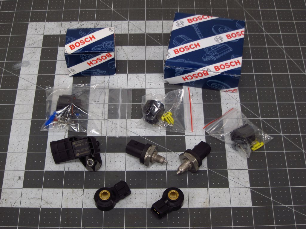
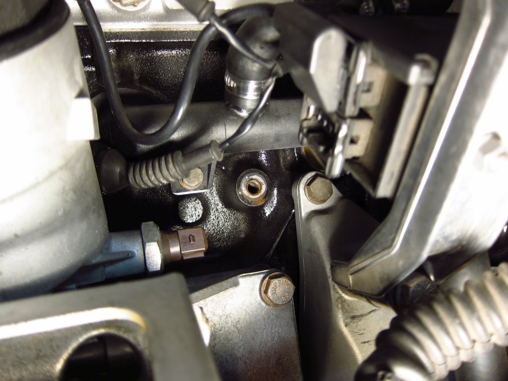
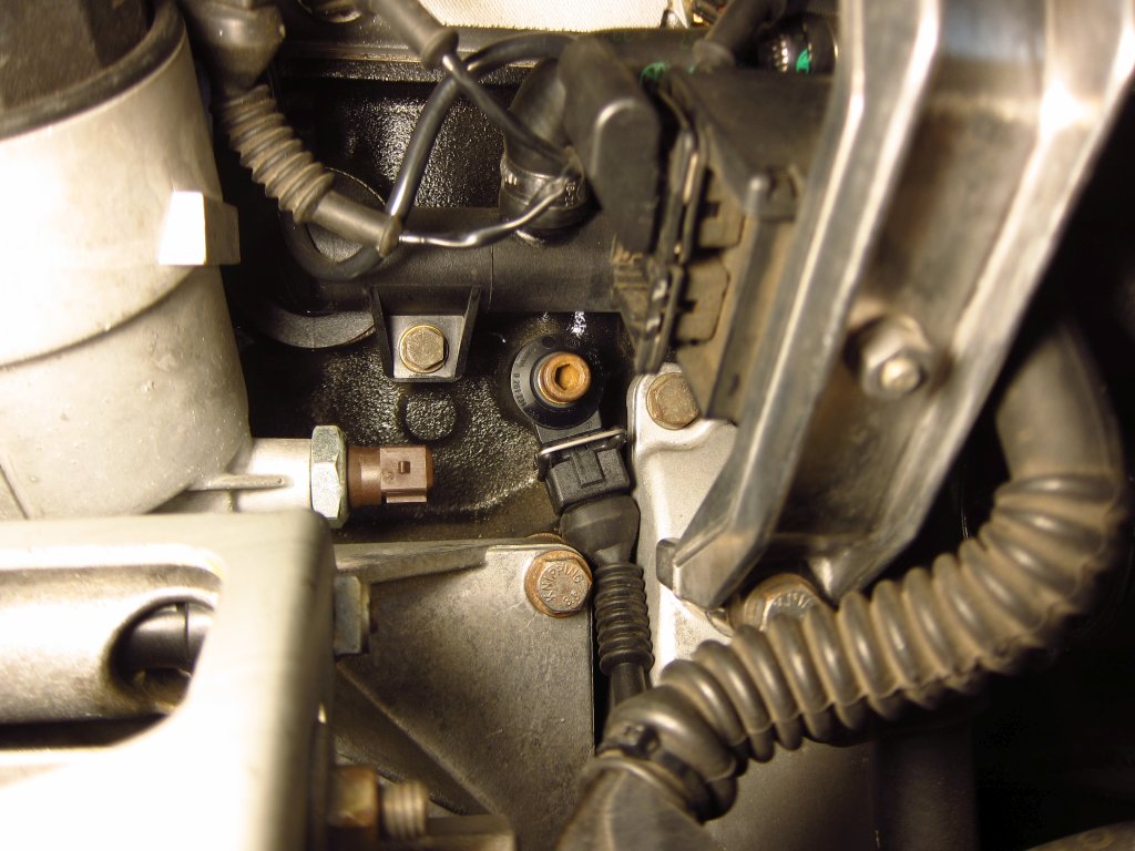
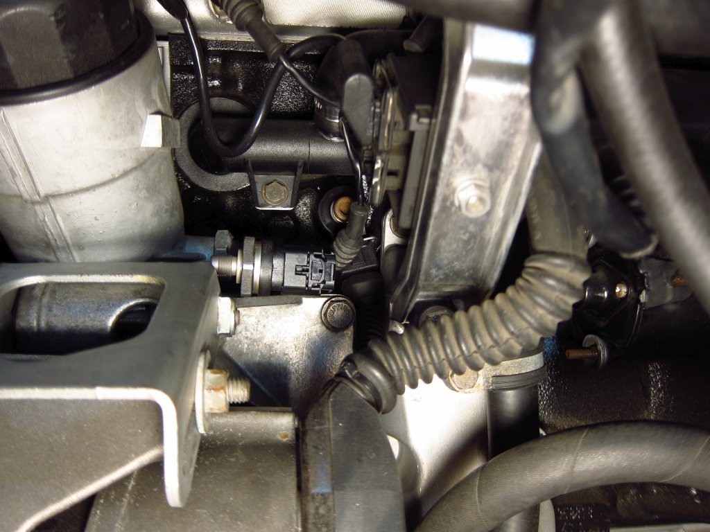
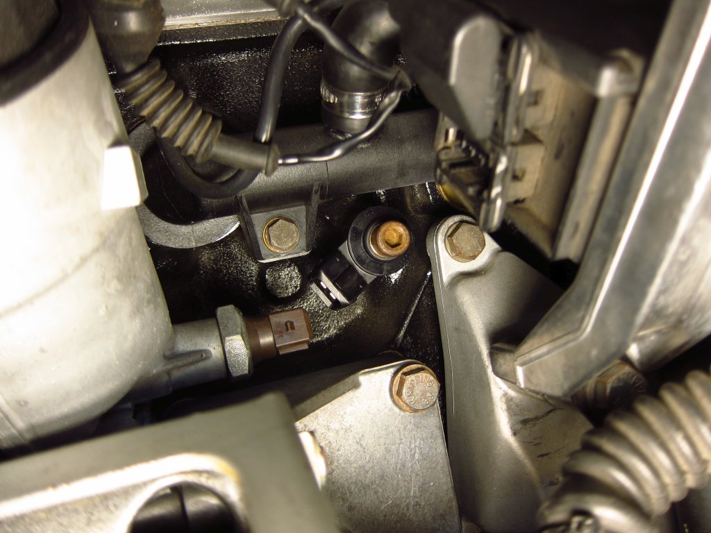
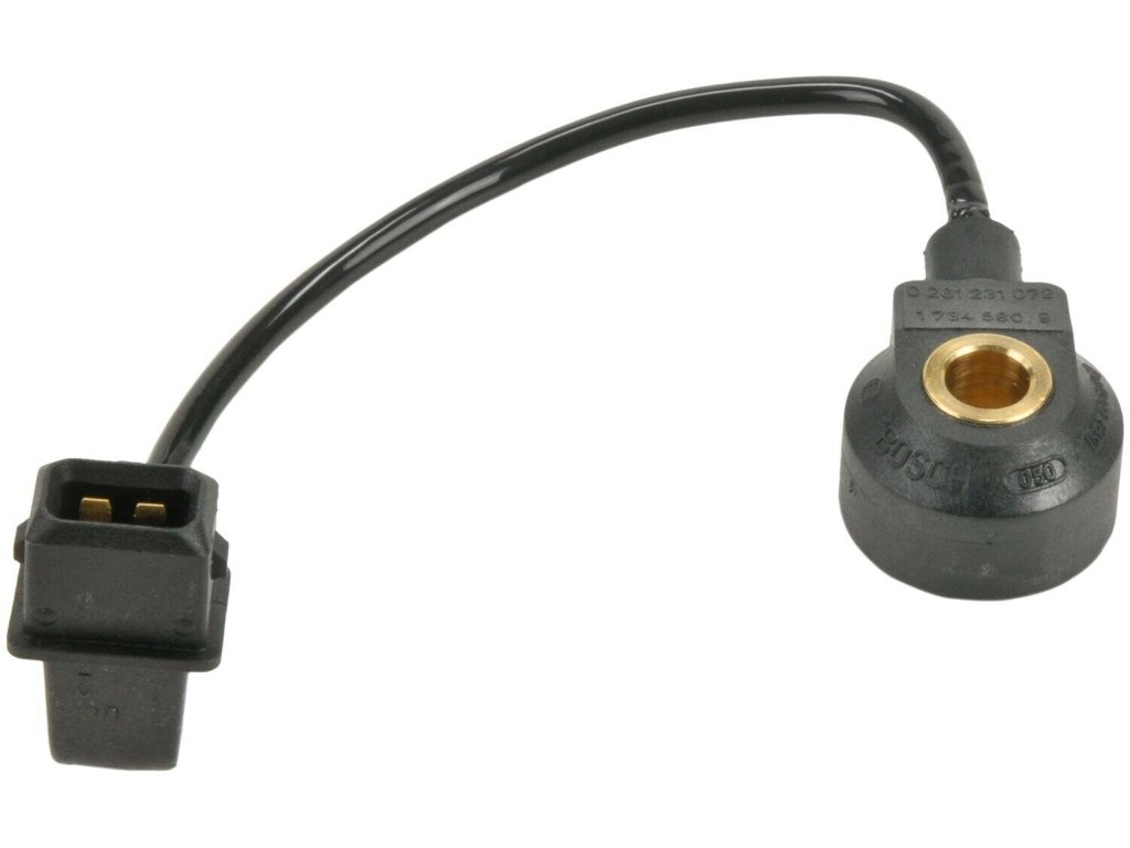
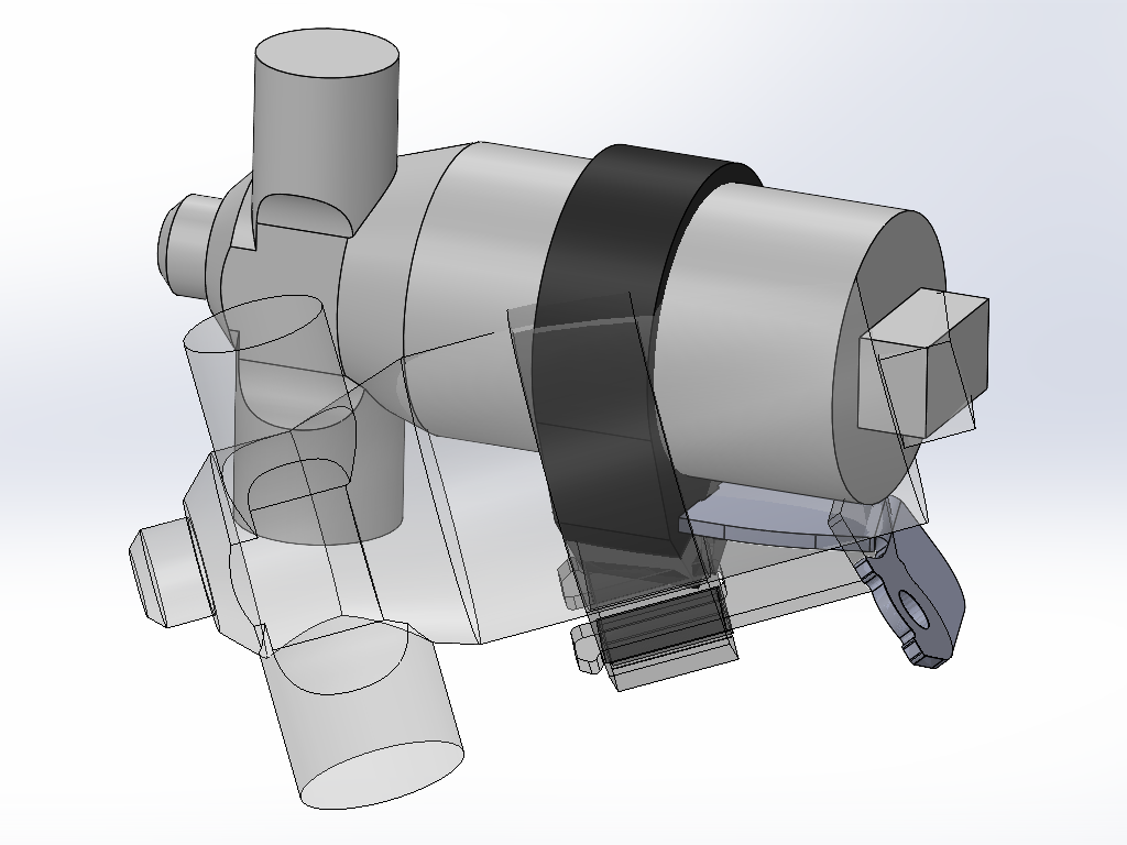
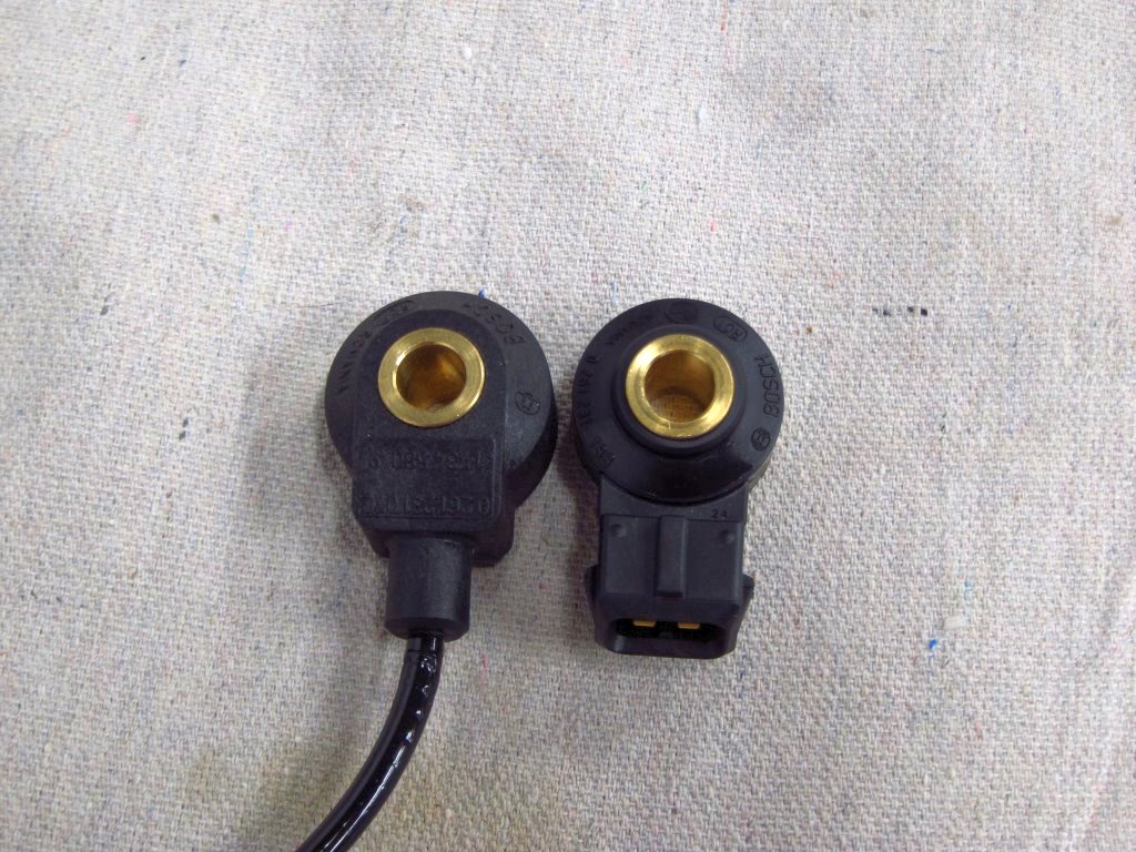
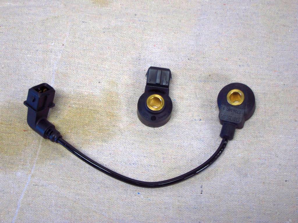
    Ha, yep, that is where I am getting my PST-F1's, knock sensors and some other bits from. Naturally, they have been sold out of the M12 to M10 adapter fittings for a couple of months! Thankfully spare M44 oil filter housings are cheap on eBay, so I will see if hacking up my spare works out well.

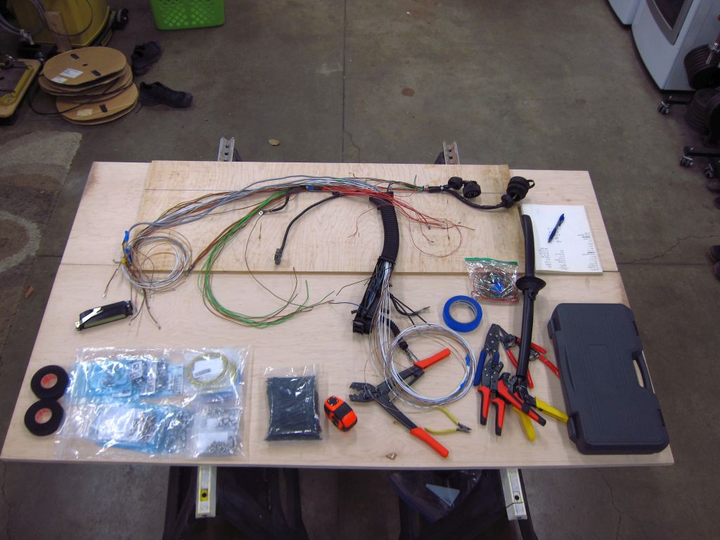
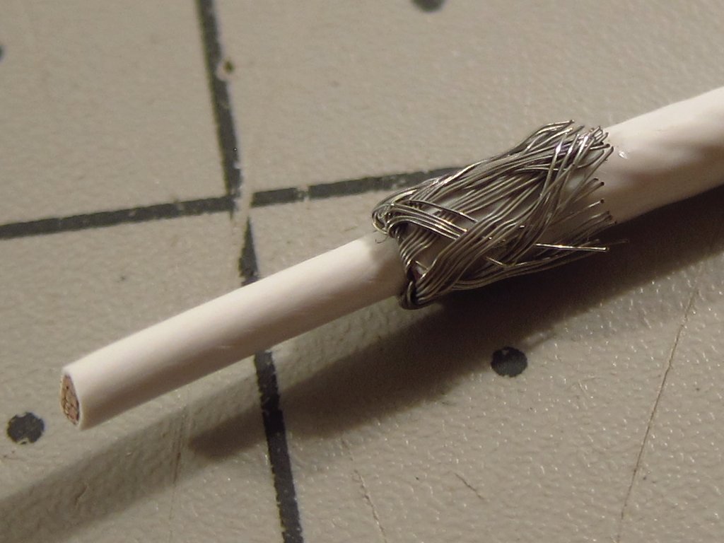
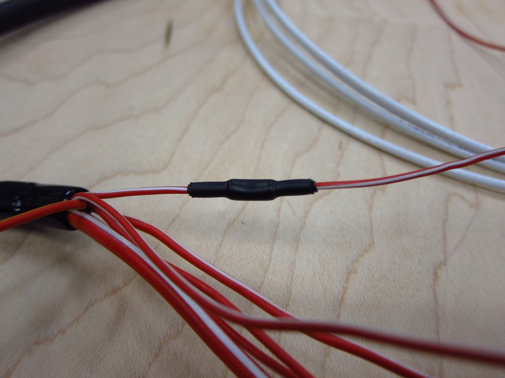
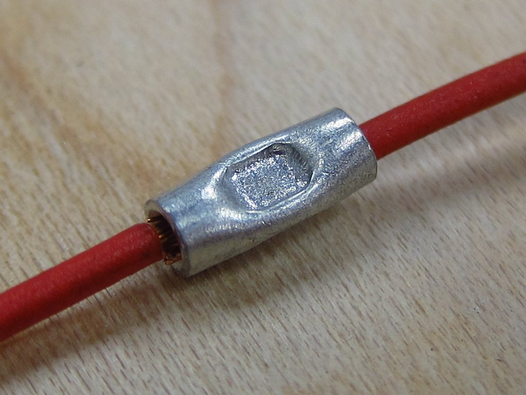
    I started doing some basic routing and roughing-in of new wire runs today. There are still a number of items and some of the heavier gauge shielded cable which I am waiting to receive, but I can get a lot of stuff into place while I wait. The plan is to just get the wires in there, but I will not be crimping/splicing/taping anything at all until I can get this fitted into the car. Once I do that, then I can make the final decisions about lengths of things and begin making permanent crimps. I also want to see how things actually end up being positioned, specifically some of the big parallel splice bundles. The big one with all of the switched 12V outputs from the main & fuel pump relays needs to have one of its smaller wires replaced with a longer run, so I either need to cut the existing splice off and make a new one with the longer wire, or just make a butt connection to extend it. The latter is far easier, but the former is cleaner. I only really pause thinking about this because the exposed copper strands from that splice are all greenish, and if the oxidation extends too far up into the wires then I might have to trim off a lot more than I want (or attack them with some fine sandpaper). Overall this is just me having fun over-thinking things, which I am sure you have figured out by now!

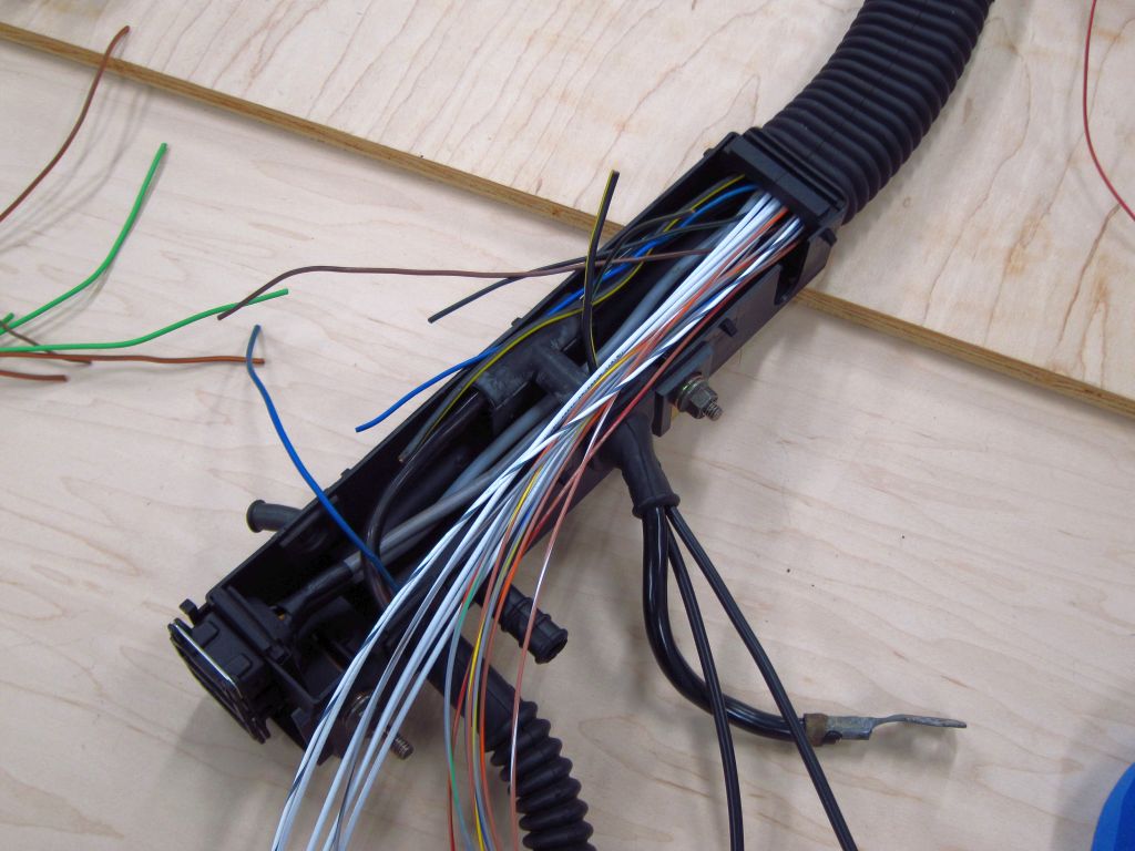
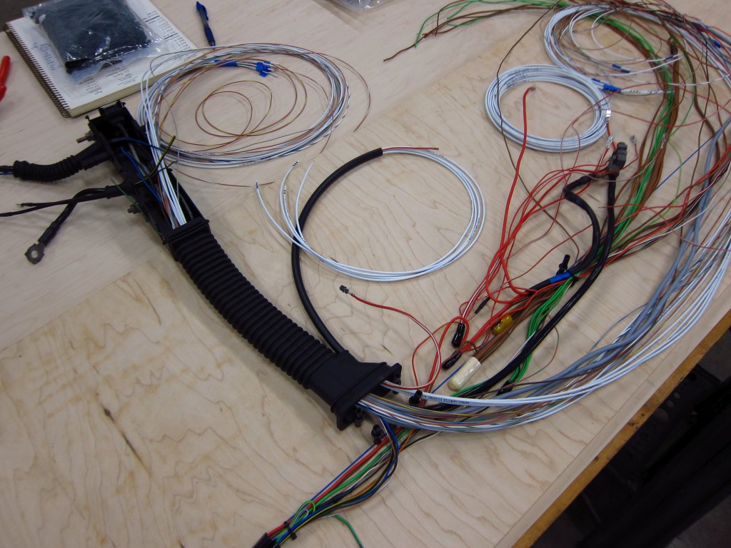
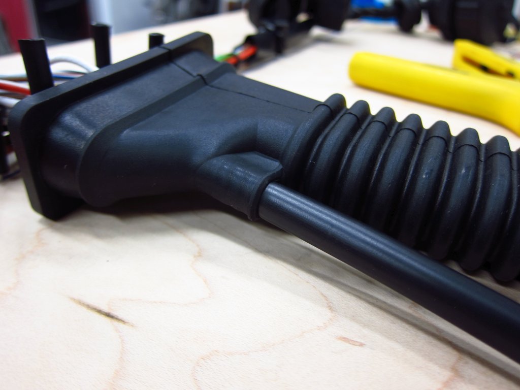
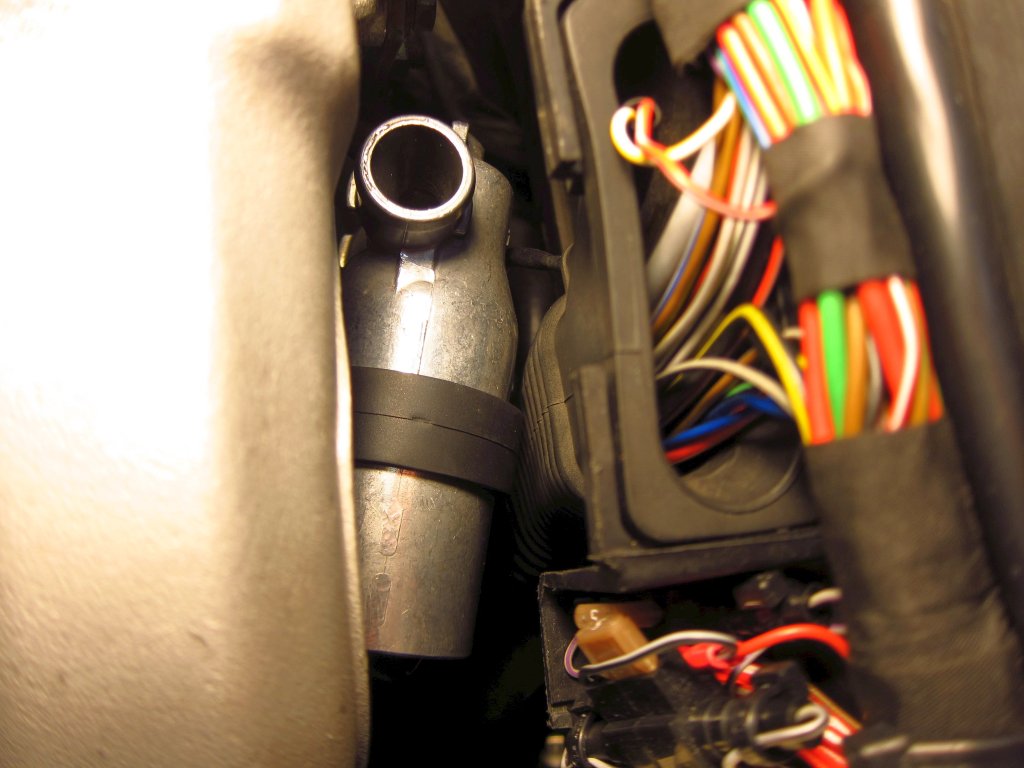
    Here's what the big wire box looks like with new runs pulled through to it. The existing wires were fine, but they all had those obnoxious splices + rubber caps which ate up almost 50% of the available volume. I understand why they did it that way, to make mass production easier, but I don't want to have to deal with the mess. There are some other splices like that in other places in the harness which I am also removing.


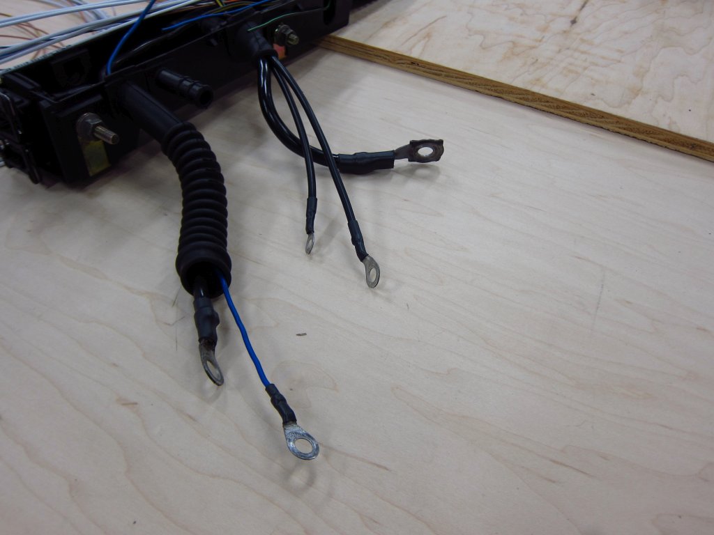
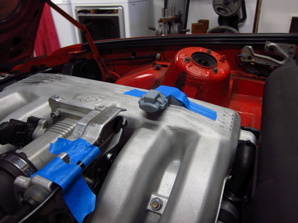
    Here's where I left things today. I am going to take it easy and spend the evening relaxing and enjoying the last few hours of 2020. It's been a rough year in a lot of ways, so I can't say I will miss it too much!


    Transaction Feedback: LINK

    Comment


      #47
      More progress...

      I finished designing a small PCB to condition the 4 wheel speed sensors' signals. It measures 32x32mm, with most of that size being driven by the wire-to-board terminal blocks. I'll 3D print a small enclosure to secure the board & wires, which will be mounted up near the knee bolster inside the dash next to the ABS computer. These little boards are in production now, and I expect to have them in a week or so. The minimum order quantity is 5, so I will have some extras that I can sell (bare board, or assembled) if anyone with a stand-alone ECU wants a quad-VR conditioner board.


      Other than that, I have not done too much since the last post since I am waiting on the last of the shielded cable & some connectors to arrive.

      Transaction Feedback: LINK

      Comment


        #48
        Lots of progress since I last checked, this is great!

        I might be interested in one of those boards to try to hack together some sort of TC on MS41
        Originally posted by priapism
        My girl don't know shit, but she bakes a mean cupcake.
        Originally posted by shameson
        Usually it's best not to know how much money you have into your e30

        Comment


          #49
          Originally posted by Northern View Post
          Lots of progress since I last checked, this is great!

          I might be interested in one of those boards to try to hack together some sort of TC on MS41
          I'll have some extras, so I can definitely mail some out. Find out what sort of signal MS41 is intended to take as the inputs. If they are 0-5V TTL inputs from Hall sensors, then this should work nicely.

          Transaction Feedback: LINK

          Comment


            #50
            Today's updates...

            I finally found a cheap crimp tool that works really well with the 2.5mm (unsealed) terminals. It is not really ideal for the JPT and SPT type terminals where the insulation grips are parallel and supposed to crimp into an "M" shape, but they are fantastic for ones like this with staggered insulation grips. They are low-leverage ones, and the crimps take 2 operations, but that is fine since I do not need to do too many of these.
            Crimpers: https://www.bmotorsports.com/shop/pr...roducts_id/364

            Here is how my new wire runs for C101 wound up (oil pressure light will now be controlled by the ECU, and I ran a new coolant gauge sender wire to eliminate the splice in the wire box). It is not production quality, but it is plenty good for this.


            Here is what the crimps look like with the "wrong" tool.


            Next, I played around a bit with different methods of shield termination. The factory wiring strips the cable sheath back a number of inches, twists the exposed shielding into a bundle, sticks plastic tubing over it and then crimps all of them together with a grounding wire outside of the DME connector housing. I have never liked that arrangement, since all of the sensitive sensor lines are packed right in there next to the unshielded lengths of ignition lines and stuff. So, I decided to see how compact of a termination I could make really close to the end at the DME terminals. It looks like I can get within a few millimeters.

            (top) A parallel crimp is the simplest way to go, but it is just too bulky once you put heat shrink over it.
            (middle) Stripping the sheath off and soldering a ground run is very compact, but it leaves jagged soldered edges poking against the central conductor's insulation which could poke through. No good.
            (bottom) Stripping the sheath and folding the shield braid back, and THEN soldering the ground termination made the cleanest arrangement. It is only marginally larger than the middle setup, and it is what I plan to go with.


            Here's how I will be doing all of the shields. First, strip 10mm of outer sheath off. Then bend the shield braid back over the outer sheath and trim it down to 5mm.


            Next, get your ground termination wire and strip enough insulation so that you can wrap the conductor around the folded shield 2-3 times (2 seems like enough). Separate 4-5 strands for the lashing, and trim the other ones down to ~5mm.


            Tightly bind the ground wire onto the shielded area. TIGHT! Also make sure that none of the strands (shield or ground) are poking up or out. It should all be nice and smooth.


            Solder it all together. Don't use too much; you do not want blobs or bulges. Just use enough to wet everything. Normally, I say that solder has NO place in an automotive wire harness, and I generally abide by that. I’d certainly never use solder to splice conductors together or attach a terminal, but shield terminations are a bit different in many ways. Also, sometimes space constraints demand it, and all of these joints will be inside the cabin where temperatures and the elements won't be a factor nearly as much as under the hood. Additionally, I will be cleaning all of these with alcohol to remove as much of the flux as possible (flux will slowly attack the wire and insulation, although it would probably take decades to actually be any kind of an issue).


            For those who are interested, here is NASA's guidance for workmanship standards in wire harnesses (or some of it at least). Being that NASA sends ships to space, and I am working on God’s Chariot which will fly majestically in the heavens, it makes sense to draw from their expertise.


            I roughed-in a little more of the wiring as well, specifically for the fuel injectors which will be controlled fully sequentially. The wiring for them now runs through the opening where the ICV wires used to come out. It is the most direct route, and it allows me to salvage the 2.5mm2 red/white wire that comes out of the fuel pump relay to power them (it is long enough to reach the injector wire box via this route, but not long enough to go down into the main wire box and then back up).


            It was a chore to stuff this 8mm sheath through the opening which was designed for a 4mm sheath. I am hoping that this will not lead to an issue in the future, like splitting open. From the technical info I can find online, it sounds like vulcanized rubber can easily stretch to 5-10x its original length and not creep or suffer other issues. I didn't take pictures of how I got it in there, but it involved folding an end length-wise, stuffing it in about an inch, forcing as many wires into the un-folded side as possible and then pulling that part through with pliers to get it in there at full diameter. Also, Windex makes for a great lubricant...very slippery, not really harmful to anything and it dries fast!


            I also replaced the rotten shrink tubing on most of the lugs. For the big ones, I used some 4:1 ATUM shrink...you can use a size large enough to slip over the lug, and it'll still cinch down onto the wire when heated. Most shrink tubing is 2:1 ratio, but if you look around online you can find the higher ratio stuff (I bought a lot of my wire and materials at prowireusa.com).


            My new favorite type of splice is the parallel splice. They are much more compact than butt splices, and I really like that the working conductors are in direct contact with each other (they overlap inside the sleeve). I needed a longer wire run for the ICV since the fuel injector wires now occupy its old exit point, and the ICV power wire will now go down through the main wire box. Although I swore I would not have any splices in the harness at the beginning, splicing on some more red-white wire from an old scrap harness was just a much more practical solution than chopping off the existing parallel splice holding the bundle of red/white wires together. Although I have plenty of large parallel crimp sleeves, the factory crimps are really nice, and most of the copper wires are pretty heavily oxidized at this point, even many inches under the insulation. It would be a chore to clean up all of the wires to get a quality connection with a new splice, so just doing it for one little wire was the way to go.


            Here's what the splice looks like before covering it up. A very good parallel splice crimper which is also very economical is in the link below. It is the one I am using.


            Also, I received a bunch of goodies today! For some reason, knock sensors are a lot bigger than I thought they would be. That reminds me of some British humo(u)r...
            Enjoy the videos and music you love, upload original content, and share it all with friends, family, and the world on YouTube.


            Transaction Feedback: LINK

            Comment


              #51
              Originally posted by bmwman91 View Post

              I'll have some extras, so I can definitely mail some out. Find out what sort of signal MS41 is intended to take as the inputs. If they are 0-5V TTL inputs from Hall sensors, then this should work nicely.
              I think my plan would be to use a micro controller like an arduino to compare the difference, either front average vs rear average or one front vs one rear and decide when to trigger.

              I'm told the ECU just wants a 5V signal from the ASC module on one of pins 80/82. I dug into this a bit in the ETM, and while there's not much info (and an inconvenient typo in the input/output labelling) it "feels" like it wants an input on pin 82, and 80 is feedback to the ASC module.

              All the ECU can do is trigger a retard table (and maybe some sort of fuel modifier that is not yet defined?), so I am probably going to have to test this to see what happens.
              Originally posted by priapism
              My girl don't know shit, but she bakes a mean cupcake.
              Originally posted by shameson
              Usually it's best not to know how much money you have into your e30

              Comment


                #52
                Got it. If you want to measure frequency accurately, you'll want to run with a microcontroller that has input capture hardwware. Regular Arduinos only have one channel. Check out the Teensy 3.2. It is the cost of an Arduino, smaller and WAY more powerful. There is a free library for it called freqMeasureMulti that greatly simplifies hardware driven frequency measurement, and the 3.2 has numerous input capture channels. You have to make sure to use the proper pins, but it'll make highly accurate measurement of all 4 wheel speed signals very easy. The only downside is that it is a 3.3V device. It'll handle 5V inputs fine, but you will need to make an output buffer to provide a 5V signal to the MS41. There are lots of commercial ICs for voltage level translation, and ti si fairly easy to do with some FETs and stuff too.


                I'm not sure how much you've worked with microcontrollers, specifically for frequency measurement, so I won't dump too much info just in case you have done a bunch of it. If not, then it's a slightly tricky thing to do well (far less simple than measuring an analog input) and I can give you some pointers. Let's just say that trying to run a main loop to repeatedly check a logic level on a pin really fast is not the way to go lol.

                Transaction Feedback: LINK

                Comment


                  #53
                  I second everything BMWman said - and nice thing about an MCU is you can trivially add some digital filtering to help with rejecting any noise, or hell, even integrate an accelerometer and go a more OEMish route. I would also especially stress going with something like the teensy over the Arduino.

                  Comment


                    #54
                    I've hardly looked into this, and I probably won't for at least another year. I haven't really looked into how I would compare, but I'm somewhat aware of Teensy (and the 3.3v "problem") just from speeduino research.

                    I haven't done a whole lot with microcontrollers, just a basic C course, a second year "intro to circuits" course, and a design class where we were let run amok.

                    I think before I do anything, I'll look at OEM setups since there must be a few good resources out there for it, but again it'll probably be a while before I get to it.
                    In the meantime I'm pretty content to follow along with your build, I don't want to sidetrack your thread.
                    Originally posted by priapism
                    My girl don't know shit, but she bakes a mean cupcake.
                    Originally posted by shameson
                    Usually it's best not to know how much money you have into your e30

                    Comment


                      #55
                      Originally posted by Northern View Post
                      I've hardly looked into this, and I probably won't for at least another year. I haven't really looked into how I would compare, but I'm somewhat aware of Teensy (and the 3.3v "problem") just from speeduino research.

                      I haven't done a whole lot with microcontrollers, just a basic C course, a second year "intro to circuits" course, and a design class where we were let run amok.

                      I think before I do anything, I'll look at OEM setups since there must be a few good resources out there for it, but again it'll probably be a while before I get to it.
                      In the meantime I'm pretty content to follow along with your build, I don't want to sidetrack your thread.
                      No worries man, despite the OCD that oozes out in my posts, I am not all serious up in here or anything. Half the fun is shooting the shit about random technical stuff. If I can get someone stoked on electrical engineering and learning new things, then it just makes the whole thing better.

                      Regarding info about the OEM traction control systems, I would be extremely surprised if there was much in the way of detailed, practical info. But then again, it seems like there is always someone out there who decided to take apart XYZ and tell everyone how it works. Now I am thinking that it might be a cool little side product to make and sell an E30 wheel speed conditioner board that enables MS41 to apply its limited traction control...

                      Transaction Feedback: LINK

                      Comment


                        #56
                        I had a chance to play around today and start figuring out where things would go and how they would fit. First, I used a 3D print of the MAP sensor and connector (Bosch provides 3D models thankfully) to see if I could clear the hood insulation with it mounted on top of the intake plenum. My preferred location would have been the flat-ish area right beyond the throttle body, but there just is not enough clearance there and I don't want to chop out the insulation (although that would probably be the simplest solution. The next best place seemed to be on top, more or less aligned with the runner for cylinder 3.

                        To check clearance, I taped my cheap USB "endoscope" camera in various places and looked at how things fit with the hood closed. You can get these cameras on Amazon for like $20. They are sort of useless for checking inside cylinders and stuff since you can't control the articulation, but they come in handy in a lot of other places.


                        Here's the clearance with the sensor sitting on top of the cosmetic rib things on the plenum. I am going to machine a depression there to give this thing a nice flat surface to sit on, and to install a little sleeve thing to allow the o-ring on the sensor to seal (I removed the thermistor & inlet portion of the sensor that stick out the bottom before printing).


                        To gauge how much clearance I actually had, I adjusted a piece of tape until it just touched the insulation. With the MAT sensor there, I have 3mm of clearance at the tallest part. I expect to gain another ~1.5mm when I machine down the ribs.


                        I investigated M50 ICV placement a bit more as well. It looks like I can keep it in the same location (roughly) as the stock one, with a little modification to the stock metal bracket and a small machined part that allows that bracket to move up ~7mm and toward the rear by ~20mm based on eyeball measurements when holding stuff in place. I couldn't get any pics, but once I 3D print some test parts I can show you what I mean.

                        The other main thing that I started looking into, and determined that I have a problem with, is the front knock sensor. If you have never handled one before (like me), they are a lot bigger than you might think. Additionally, the ones I bought are even larger because they have the 2-pole plug molded into them, at a slight upward angle. The stock ones have the same size body, but no giant plug (or receptacle that needs to also fit onto it). Here's the existing boss where the front knock sensor goes. Thanks to the engine mount arm, water pipe, alternator mount bracket and oil pressure switch, it is pretty crowded in the area.


                        The only remotely plausible way to get the sensor + plug + boot in there is to position it like this. It is not jammed against either of the brackets, but there is at best 0.5mm of wiggle room. If I skipped the rubber boot and just used some wire seals instead, I think that it would likely be OK, but I really would prefer not to skip the boot since I have to tie the cable's shield to one of the terminals and don't want it exposed.


                        Furthermore, the oil pressure + temperature sensor is fairly large thanks to its connector, and since I am going to skip machining the oil filter housing and just use an M12 to M10 adapter fitting, the sensor will stick out even further than the pressure switch. Boot or no-boot, I don't think that the knock sensor can go here.


                        If I wanted to have the right amount of clearance for it, it would need to point this way, and the oil sensor could not possibly go here.


                        So that brings me to a decision between 2 options.

                        Option 1) Install the oil sensor in the back of the head where there is an M12 plug which I think (still not sure, trying to confirm) is for the head's main oil gallery. There is enough room between the head and firewall that the sensor, adapter and connector will fit fairly well. This way, I can keep the knock sensors I have and use them.

                        Option 2) Put the oil sensor in the oil filter housing, but get stock M42 knock sensors. I assume that the sensors themselves are either approximately the same as the ones I have, or at the very least tuned approximately right to work with my bore size (87.5mm, vs 84mm stock). The stock sensors are a lot more compact since they just mold the wire in and have the connector at the end of the small harness (same connector as the sensors I have too). In fact, the Bosch branded stock ones are a little cheaper than the KS4P sensors I already have, which is a big plus. I am 99% sure that these will enable everything to fit in there, with the only drawbacks being that the integrated harnesses will make things a little cluttered and these will probably become NLA at some point.


                        That's it for today. Progress is going to be a little slow as I make measurements and finalize positioning for things, but at least it all looks fairly plausible at this point.

                        Transaction Feedback: LINK

                        Comment


                          #57
                          I got a little more done today, this time focusing on the ICV and how to mount it. Thankfully it does look like I can position it behind the intake manifold like the original one, although it is a tight fit!

                          Here is how it will sit (solid) relative to where the stock bracket holds the ICV (transparent).


                          This is how the new one will look compared to stock.


                          It is a part that can pretty easily be laser cut from some 3/32" (2.4mm) mild steel sheet and then bent in a vise.


                          As far as being sure that it works, I 3D printed a number of test parts to hold the M50 ICV. Looking at the M42 and M50 ICVs side by side, you can see how much longer the M50 one is.


                          It took a few tries to get things exactly where I wanted them.


                          Here's the final 3D printed test bracket assembled onto the ICV and grommet.


                          You can see that it is a TIGHT fit back there, but there is enough clearance everywhere. This thing sort of nests into the manifold runners a little, but there are 3-5mm of space all around. I have no idea how awful it will be to get the lower hose on there, but I guess I will find out. Selecting hoses and adapters is the next thing I need to look into, but now that it is in place I can narrow things down a little.


                          Transaction Feedback: LINK

                          Comment


                            #58
                            I got the stock M42 knock sensors today and did a quick fit check. These are definitely going to fit better, and I can keep the oil sensor in the filter housing.

                            Here is how a stock one fits with the wire exiting toward the rear, which is how I think I want it to go so that I can install the receptacle in the bottom of the wire box and have the sensors plug right in. Even with the other stuff in place, it is not interfering.


                            Here's how it looks with everything out of the way.


                            I could also turn it around and have the wire come out the front, so I have that as an option if necessary.


                            Here is a comparison between the M42 stock sensors and the KS4P sensors I had initially wanted to use. The stock ones are actually slightly larger, but having the integrated wire makes it a lot shorter overall.


                            Also, I put together one of my little wheel speed sensor boards. Unfortunately, I mixed up the footprint for the 5V regulator and fried it instantly lol (you can see the little burn spot where the magic smoke escaped). I corrected the issue and ordered a new set of boards. After removing the regulator and just powering the thing directly with a 5V supply, I was able to verify that one of the conditioner chips was working correctly, but the other one got cooked. Oh well, live and learn, and double check the datasheet!


                            Transaction Feedback: LINK

                            Comment


                              #59
                              Originally posted by bmwman91 View Post

                              ...

                              Also, I put together one of my little wheel speed sensor boards. Unfortunately, I mixed up the footprint for the 5V regulator and fried it instantly lol (you can see the little burn spot where the magic smoke escaped). I corrected the issue and ordered a new set of boards. After removing the regulator and just powering the thing directly with a 5V supply, I was able to verify that one of the conditioner chips was working correctly, but the other one got cooked. Oh well, live and learn, and double check the datasheet!

                              Ha, been there. Spent hours and hours a few weeks ago just to figure out I was pulling down a line I should have pulled up on my proto cluster board... only to load a buggy binary and lock myself out of a $50 MCU (all the safety reset goodies on the ti chips can be a bugger early on, and I should know better...)

                              Keep at it man, looks like great progress.

                              Comment


                                #60
                                Originally posted by JehTehsus View Post

                                Ha, been there. Spent hours and hours a few weeks ago just to figure out I was pulling down a line I should have pulled up on my proto cluster board... only to load a buggy binary and lock myself out of a $50 MCU (all the safety reset goodies on the ti chips can be a bugger early on, and I should know better...)

                                Keep at it man, looks like great progress.
                                Ouch. Did you have some of the code protection / encryption stuff enabled? I have always been paranoid about that with the Microchip devices I've worked with in assembly since it sounds like you will very quickly end up with an unusable device if you make a mistake. Thankfully, most of them are like $5, rather than $50!

                                Good work on the cluster project BTW. I have been following along with it and it is pretty cool. The stock speedo and tach are certainly nowhere near accurate or linear, and I've always thought it would be cool to have one powered by proper modern electronics, while still looking stock(ish).

                                Transaction Feedback: LINK

                                Comment

                                Working...
                                X