Announcement

Collapse
No announcement yet.

M42 Head Gasket Blown, Project Thread

Collapse
X
 
  • Filter
  • Time
  • Show
Clear All
new posts

    #61
    Originally posted by ForcedFirebird View Post
    Great attention to wiring detail!

    Amazing how much time and money add up in the details, but it's soooo worth it in the end.
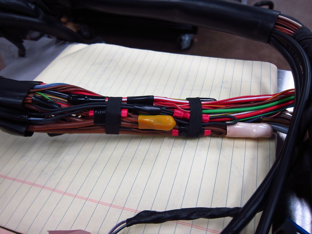
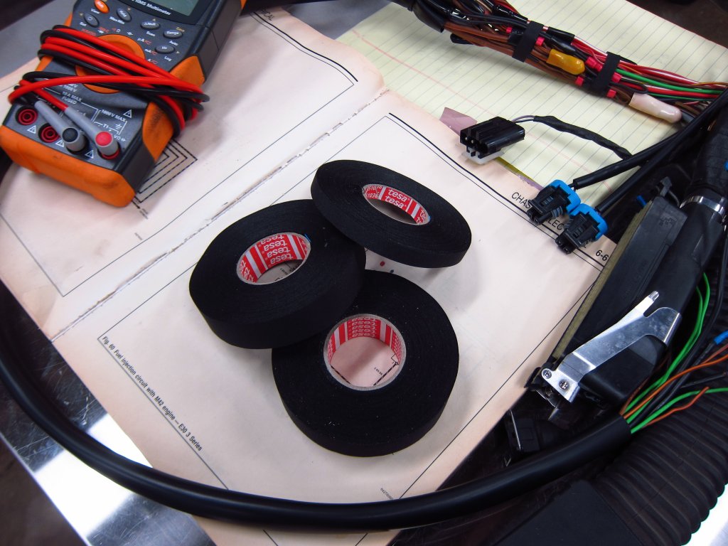
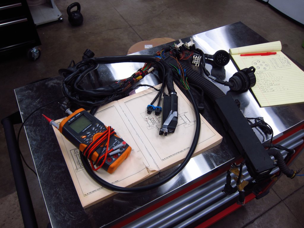
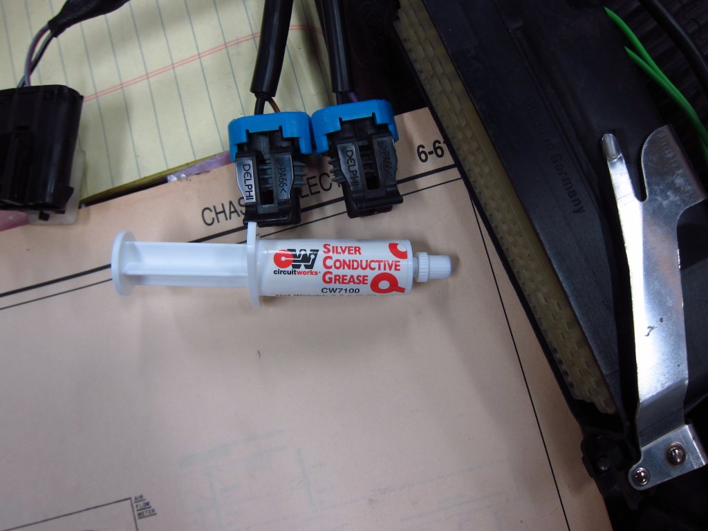
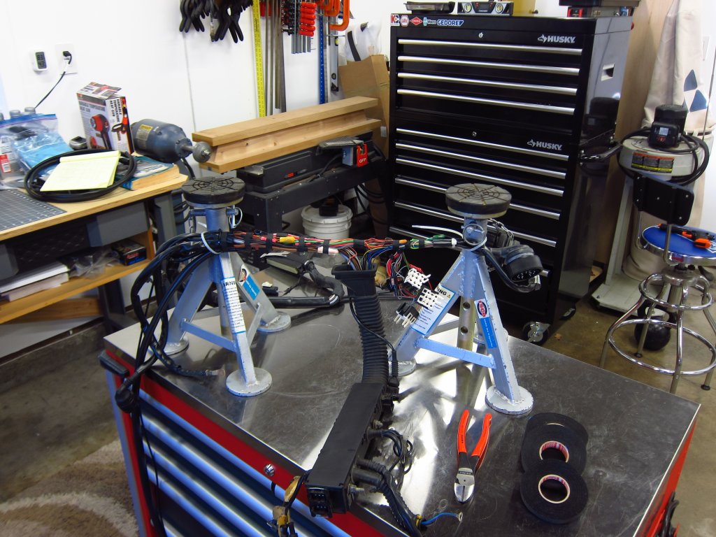
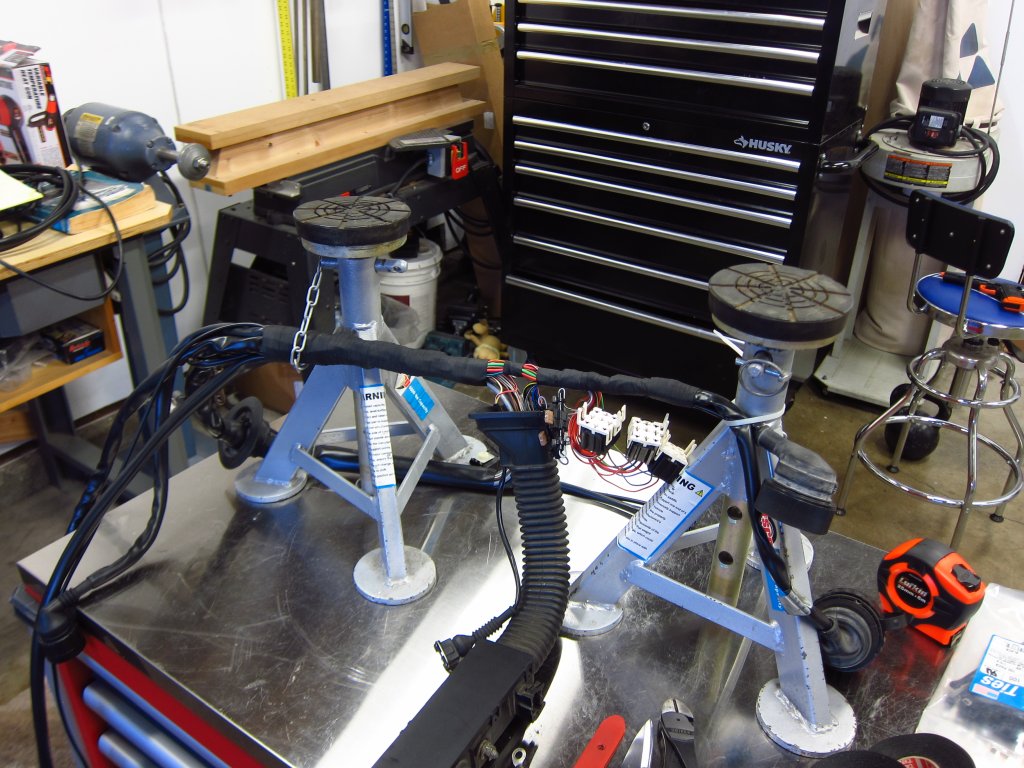
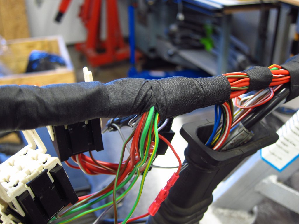
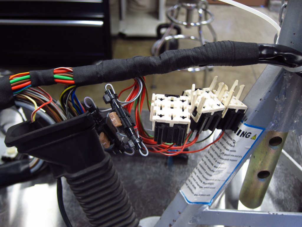
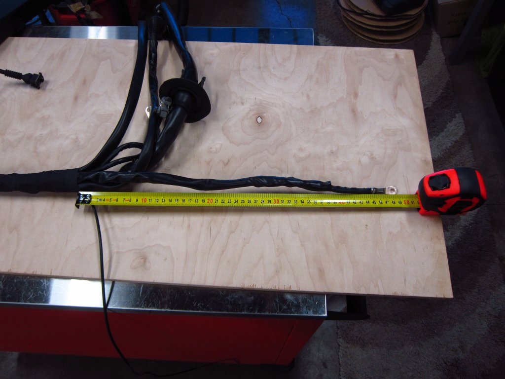
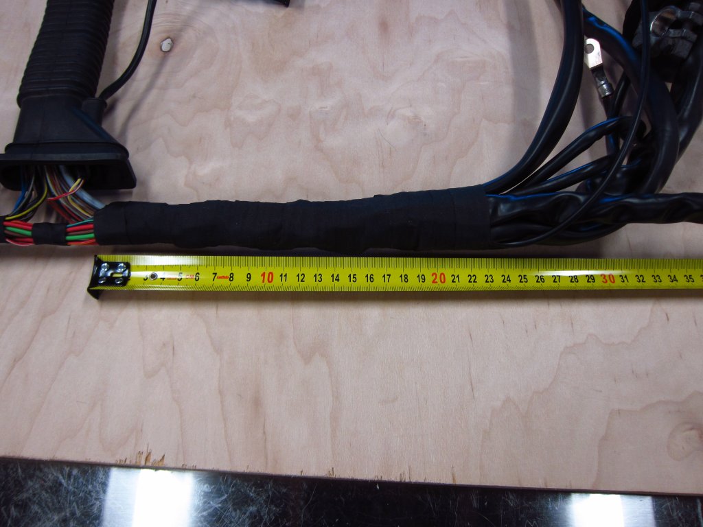
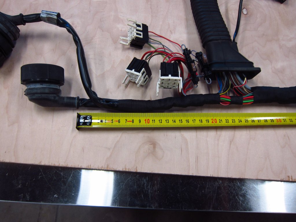
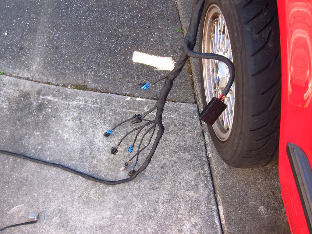
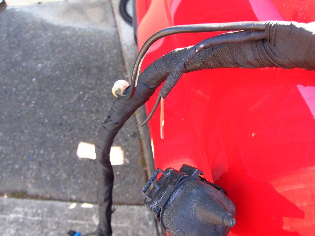
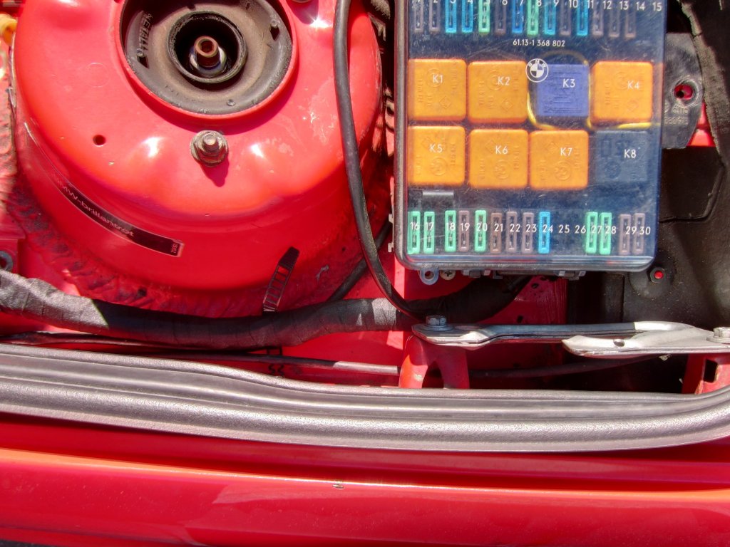
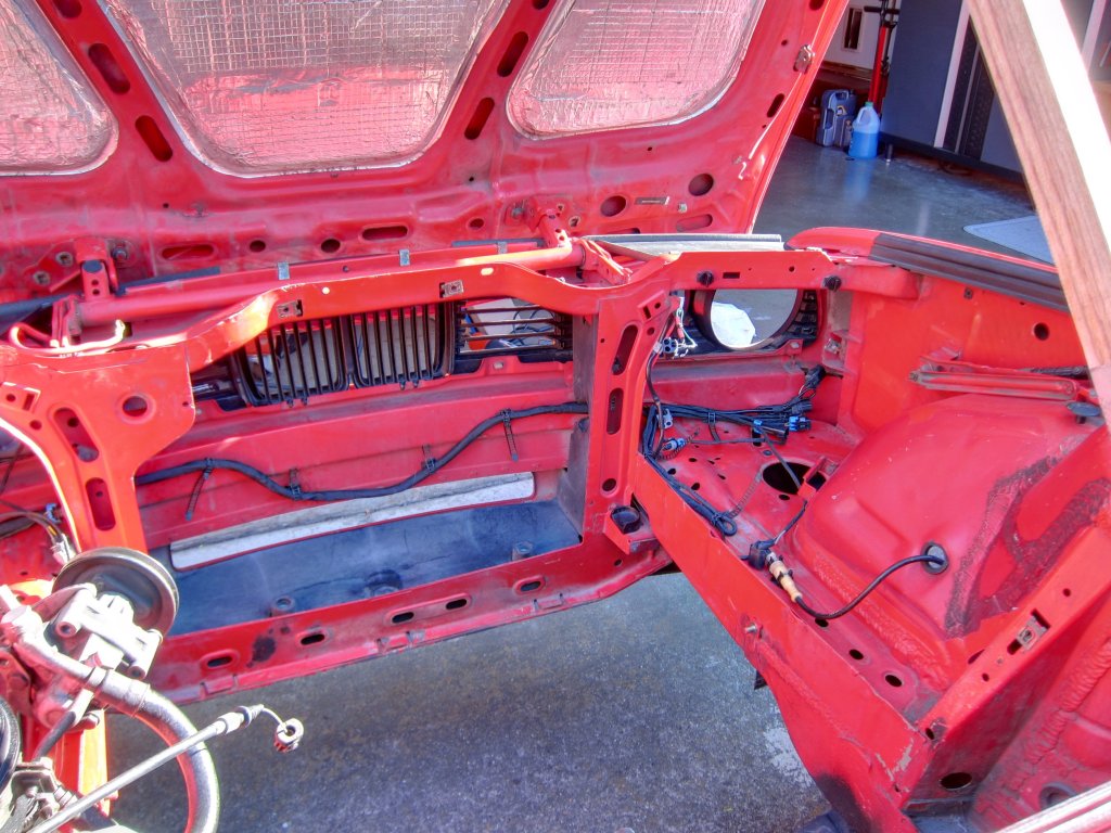
    Thanks. Man, it takes a load of time to do the wiring, or at least it does when you are really concentrating on proper strain relieving and routing. Lots of test-routing, measuring, pre-bending, etc. I know it is not really necessary since some super sketchy stuff that people do with wiring lasts decades, and part of me is paranoid that I am over engineering this so badly that it will end up breaking in some other way lol. The saga of this car and engine is so long and filled with disaster that I don't quite think I can be objective about it!


    Also, is there a way to multi-quote people? I am too lazy to manually input the tags, and they are more complicated than in the old vBulletin, but it is dumb to have to make a separate post to be able to use the "quote" button for multiple posts.

    Transaction Feedback: LINK

    Comment


      #62
      Great work as always! I have a quick question/wanting some feedback about wiring. I'm rebuilding my injectors and when removing the injectors the wire cover cracked in half. One of the problems I found out that I'm having is the clips that hold the connectors were missing so they weren't properly seated and were causing me to have a lean issue. I'm thinking about soldering in new injector connectors and covering the fuel injector harness with cable sheathing and heat shrink. I know it would work, but I'm a little worried about heat cycling and wear/tear. Figured I should ask someone with a little more experience than me lol


      My Daily Driven 318is

      Comment


        #63
        Yeah, those wire clips are pretty important! Luckily they are cheap and easy to get.

        As for securing the cover on the injector harness "box" thing, I would not use heat shrink tubing. It makes accessing it a pain in the ass, and unless you get special high temperature stuff, the regular stuff will soften at the temperatures that can occur in that area. I would just go with some of these:
        McMaster-Carr is the complete source for your plant with over 595,000 products. 98% of products ordered ship from stock and deliver same or next day.


        I have a question as well. My fuel rail has been sitting for months now. I dumped out as much fuel as I could, but I am sure that a couple of ounces were still there, which dried out. My experience with letting gasoline dry is that it leaves all sorts of nasty goo / varnish stuff. Should I try to shoot it out with some carb cleaner, or am I just being paranoid? Sssquid checked over my injectors and they are all nice and clean, so I certainly don't need a chunk of gas goop plugging one up after the first start!

        Transaction Feedback: LINK

        Comment


          #64
          I should've specified a little more the box itself snapped haha

          Since I just finished cleaning my injectors my fuel rail has been out for a bit. I was planning on just spraying the fuel rail with brake cleaner to knock anything loose from inside. Im replacing the fpr so there's enough space for debris to fall out. Hopefully someone has a more elegant solution!


          My Daily Driven 318is

          Comment


            #65
            OK, more updates. Progress is a little slow since I am still waiting on 2 large shipments of parts (basically everything), which is fine since I can satisfy my OCD with the wire harness lol.

            As far as non-wiring stuff, I did get the oil filter housing reinstalled. Twice actually. The gasket kind of squeezed out by ~1.5mm in a few places thanks to the gasket sealer spray acting like a lubricant, and while it was most likely fine, I was paranoid that it may have torn and could have made an oil leak. So, I yanked it off and spent a bunch of time scraping the stuck bits off and cleaning things with acetone. I had planned to install the second one dry, but naturally I managed to scratch the gasket surface a bit scraping the first one off, and while some light 800# sanding mostly took care of it, I ended up spraying the new gasket as well to try to guarantee zero oil leaks. The second gasket also squeezed out a little, but that's been the case every time I've ever used it on thin paper gaskets and never had a leak. The OCD was strong! I also took the opportunity to really blast-out the inside of the filter housing with brake cleaner after chasing the threads for the pressure switch, which had bits of RTV in them from some past life. Maybe I just need to sleep more, because I was super paranoid about getting any crud in the "clean" side and went through most of a can of cleaner (it is an M44 filter housing, with a removable outlet check valve, making it way easier to be sure that crud has escaped during cleaning). Anyway, it's on again, and the 6 bolts are torqued to 10 ft-lbs, which feels like about the maximum that they will tolerate. I've tried to find specs for these and it is all over the place from 8-18 ft-lbs. Being that it just needs to hold the gasket down against ~60PSI oil, 10 ft-lbs seemed plenty. The first time I did the housing I torqued things to 12 ft-lbs, and it caused one of the bolts to yield. Thankfully I had spares.

            OK, pedantic ruminations on a critical but very simple assembly step are done now lol.

            As far as the harness goes, I am basically done with the changes and just need to triple check everything with my multimeter to make sure that everything is connected exactly as planned. Once it all checks out, I will re-wrap it with new Tesa tape.


            First, for the new terminals that I was crimping on, I ran a couple of tests on things. The terminals are not the overpriced "BMW" ones, rather they are the ones straight from the manufacturer (TE/Amp) that I bought on Digikey. I don't have the exact crimpers specified for these terminals (they are stupid expensive), but my sets of generic ratcheting ones for open barrel terminals are mostly fine. However, the wings that are intended to grip the wire insulation were a bit long, probably because the manufacturer's crimping dies are different than mine, and they looked like they would mangle things without some trimming. So I cut ~1.5mm off of them and they came out looking like they would properly dig in to the wires' insulation.

            Also, for reference, new terminals are super difficult to remove from the plastic connector housings. Either the retaining fingers are stiffer, or they have sharper edges from stamping, but they are harder to remove than the old ones without some help. I found that (for the 2.5mm round ones) running the extraction sleeve over them a couple of times before installation made them much easier to remove since it took a little spring out of the fingers. For the rectangular standard power timer terminals (for the ignition coils), some light squeezing of the retaining fingers with needle nosed pliers had the same effect (no pics of those, will not finalize that until it is all in the car so I can cut them to length).


            ​

            I played around with a few different dies to get the crimps clean and tight. This was one of the intermediate results. While it was passable, it was a little messy and I was able to get cleaner results later. Sadly, without buying the super expensive crimper from the manufacturer, you just won't get the same kind of crimps that you find on the original connections (production environments use even more expensive automated machines to do the crimps!).


            I then did a few of the 7-position circular connectors. One for the MAF converter to plug into the factory AFM connection, and then a pair for the wide-band O2 controller. I used the bigger 7-pos connector since I utilized all 6 of the wires coming from it, with new pulls of wire into the main harness for the 0-5V wide-band output and a status indicator LED.


            Here's how it will be located after the harness is back in the car. The controller will be tied to the main ground run, and the connection will be back by the firewall.


            I then did the connector for the MAF converter. As mentioned in a previous post, I repurposed the unused LLCO line (moved from position 3 to position 6) to provide a 12V source, with an inline fuse installed up near the relay bank.


            A concession I made was to use a few butt splices here and there up in the main loom. One was added to the wire that grounds the shields for the cam+crank cables, to tie in the shield from the WBO2 0-5V signal shield; one was added to the ground for the O2 sensor heater (formerly, it is now the WBO2 controller analog ground) to tie in a dedicated ground reference for the WBO2 0-5V output; one was part of an entirely new run of wires for the indicator LED ground and the WBO2 heater ground which (according to the installation manual) should be separate from the electronics. These are not my favorite, but done with the proper crimp tool and with strain relief allowances they are just fine. I just made sure to give each incoming wire a few millimeters of slack and then tape them onto larger parallel ones in the same bundle to prevent tugs on the splices. It's all going to be under heavy harness tape in the end, so none of it is going anywhere. Again, OCD overdrive here lol. I have seen (and done!) way sketchier wiring jobs in the past that have survived more than a decade.


            Speaking of harness tape, here's what I am going to be re-wrapping things with. Tesa 51036, which is more or less the latest and greatest high temperature engine harness wrapping tape. Just based on handling it, I think that it is a LOT less likely to suffer the same fate as the nasty original stuff. Part of me wants to pull the whole chassis harness out of the car and re-wrap it all!


            Here are the connectors that I added on the cabin-side of the harness. One is for the data logger connection to the 0-5V WBO2 output (the controller also has a simulated narrow-band output, which is connected to the Motronic's original O2 sensor input, and I also made a couple of needed changes to the analog ground connections since it differs from the stock one and needs to be done properly to get the Motronic to correctly run with it). The other is for hooking up a status indicator LED for the WBO2 controller. I will probably mount it in the upper-right corner of the plastic cover that hides the Motronic inside the glove box.


            The connectors again, and also a little tube of OCD-silliness that I got on McMaster. I will be applying this to the ground cable lugs and high current ground joints on the engine (alternator strap, engine to chassis strap, chassis to batt- strap, alternator bracket to block, right mount arm to block). It is obviously overkill, but I use it for other non-car stuff too so it's good to have around. For fun I think I will get my 6.5 digit bench meter out there and do some 4-wire resistance measurements to see if the conductive goop does anything.


            The only remaining open item is trimming the ignition coil leads to length, which must be done once everything is reinstalled in the car. Extra care will be taken to strain relieve the harness for those since it will jump form the chassis to the engine and be subject to all of the motion involved there. My old COP setup with a hacked stock harness made it 14 years, and this new one will be done better than that.
            Last edited by bmwman91; 04-22-2020, 10:05 PM.

            Transaction Feedback: LINK

            Comment


              #66
              Nice job. I have similar ratcheting crimpers with the interchangeable anvils made by Blue Point. Was just repairing an ix harness today with it using those silicone caps and open barrel crimps as the factory uses. I had a nice pair of crimpers that were perfect for them, but they gave up the ghost after about 21yrs of use - can't find another set like them. :(

              As far as the longer fingers, they are meant to curl in and poke the wire insulation. When they come in the package, they are spread too far, just gotta roll them a little to get them started, then the "step" in the crimper anvils will crimp the insulation and bare wire at the same time. Takes a little practice, but have gotten used to the new pair - the old ones were just plain pliers-type with 5 or 6 different "M' openings and I would have to double crimp the insulation/bare sections individually.
              john@m20guru.com
              Links:
              Transaction feedback: Here, here and here. Thanks :D

              Comment


                #67
                Yeah, I tried to find the right length for the insulation grip fingers so that they would still dig in, but not so much that they went all the way through and either out the other side or all curled up inside. I also generally find that I do two crimp operations per terminal. The dies have the narrow and wide sections in each opening, but they are not quite wide enough fully crimp the part that grips the bare wire strands, so I make a second pass to get that crunched down.

                I do have a set of Metri-Pak / Weather-Pak crimpers and terminals, which is what I used for the 2 "new" connectors that I added. Those are a hell of a lot easier to work with then the TE/Amp JPT/SPT/2.5mm round systems. It also irks me that BMW saw fit to take all of their JPT connector housings and heat-stake the inlets so that the terminals cannot be removed. Back when I was looking at modifying some of those connections for a stand alone ECU, I realized that I would have to run a 3mm end mill through the staked sections if I wanted to salvage the terminals...stupid! At least new housings are widely available still.

                Transaction Feedback: LINK

                Comment


                  #68
                  OK, more progress today. All new or changed electrical connections were successfully tested for continuity at their respective endpoints, so I re-wrapped the section that goes up on the firewall. Thankfully this is a very simple wire harness (at least for a car with fully electronic fuel & ignition), so it was very straightforward to do and keep the tape laying neatly. The Tesa tape is a little stretchy, but not much, so paying attention to how it is directed over bulges and stuff is important if you want to keep the layers neat and have minimal hiccups showing.

                  To prepare for wrapping it, I rigged up some stuff to hold it in approximately the position it will sit in the car, with cables pre-bent in the way that they would be in the car. The new tape has very little give in it and the adhesive is good, so wires on the outside of the bundle which will be in contact with the tape will have essentially zero ability to slide around later. So by pre-bending the various sections before taping, each wire would be more or less in its final position with minimal pulling on the connectors they terminate into. As far as I can tell, all of the wires in this thing already have lots of slack in them inside the plastic sheath sections, so this is maybe just me being nit-picky, but anyone who has chased down a fault in a wire harness knows how much of a pain in the ass it is. So, I am seeking to avoid ever having to dick around with this thing again.


                  Here it is after wrapping. The left part used the wide 25mm tape, and the smaller right section used 19mm tape since it was shorter and needed the relay wires routed through it. I have a roll of 9mm wide tape as well, but it was only used in a few spots to hold the bundles together before I taped over it with the bigger stuff. There is now zero electrical tape in there anywhere. Even the decent quality stuff, like 3M Super 88, was starting to leave black goop on my freshly cleaned wires. So with that crap gone, I expect there to be zero goopy tape mess in there within my lifetime.


                  The only part of the entire thing that needed any extra work was the section where the relay wiring breaks out of the main loom. I did one pass over the whole section, and then a second pass in the opposite direction just in this area to ensure that the exiting wires won't pull the lays apart. All of the relays and inline fuses that I added are now sitting pretty in just the right place.


                  Just in case anyone else ever wants to re-wrap theirs, here are some shots of the lengths of things for reference. I based the start & stop distances for the tape on the harness that is in the car now and a partially-dismantled spare. The distances vary by ~1cm between the two, probably from age and shrinkage, so I applied the tape for maximum coverage. If it is somehow a problem when I get it back in the car, I can just unwrap some, trim and add new pieces of tape to cap the ends (the 4 "ends' are all terminated by adding a piece of 19mm tape and wrapping 2-3 layers of it in the same direction as the cut end they cover).


                  Every store is sold out of 99% isopropyl alcohol (and paper towels, and TP) around here, because idiots, so I am going to have to wait a little bit before I remove the tape on the Motronic end. Those wires will also get a full cleaning and new tape. Other than that, it is mostly a waiting game for the rest of my parts to show up. BMW of Silver Spring is waiting on a couple of parts to ship over from Germany, and I am having them check that the OEM engine mounts are properly constructed (see here for the issue starting at post #7). If they are wrong, then I will probably go with the Garagistic 80A poly mounts, which I hope are not as insufferable as the OEM M30B35 mounts.

                  Also, I have received my RHD Engineering lightweight flywheel (7.4lb), as well as a new stock M20 clutch kit. It has a couple of small dings in the friction surface, which is unfortunate. One was just catch-able with a fingernail, but a little quick lapping with a diamond hone took care of it and none of the 3 dings can be caught with a fingernail (can you find all 3 in the photo?). The relatively low price of the flywheel, and the fact that it shipped directly from Taiwan, would normally give me some pause, but RHD seems to have many satisfied customers across various BMW forums, and there are no reports of them coming apart at high RPM (which is really my only concern). Per Rama, RHD's owner, these flywheels are good above 10,000RPM which is well beyond anything that it will see in my car, and I am only going to be making ~200bhp as far as I can tell.

                  There is a shop about 30 minutes from me that does dynamic balancing of cranks/flywheels/etc, so I will be dropping off the flywheel and pressure plate with them for co-balancing in a week or two once my new pressure plate bolts show up with the rest of the parts.


                  Last edited by bmwman91; 04-24-2020, 06:57 PM.

                  Transaction Feedback: LINK

                  Comment


                    #69
                    Oh and also, here are a couple of additional items, one of which may be useful to other E30 318iS owners. Last year I took apart one of my spare harnesses entirely and made a proper full-color diagram of the whole thing. The factory wiring diagrams out there are fine, although there are several mistakes and omissions of splices in them it turns out, but nowhere anyone would likely ever have to deal with. I am thinking of getting it printed on a D-size sheet and hanging it in my garage as "art"!

                    Here is the diagram of the 100% stock harness:
                    http://www.e30tuner.com/assist/m42w..._318iS_OEM.pdf


                    I also have a customized copy that I made which reflects all of the changes I made to my harness. Drawing these things is tedious and boring, but I figured that capturing all of the changes accurately now was better than forgetting about it and then me trying to remember what the hell I did when (God forbid) someday there is an issue. See if you can spot the differences!

                    http://www.e30tuner.com/assist/m42wi...ess_MM2100.pdf


                    EDIT: Fixed links. I really do not like the new forum software. Get off my lawn...
                    Last edited by bmwman91; 04-24-2020, 07:37 PM.

                    Transaction Feedback: LINK

                    Comment


                      #70
                      Phenomenal! Proper tape, nice diagrams, inspirational.

                      Comment


                        #71
                        Thanks. Hopefully it all actually works!

                        I plodded around a little more today on some odds and ends related to this. The block is nicely painted, but I wanted the alternator bracket & engine mount bracket bosses to have metal-metal contact when bolted down, so I scraped the mating faces clean. All threads in the outside of the block were chased out too.

                        The main thing I did was wash out the engine bay since it was really gross. The car saw a fair amount of off-road driving last year (200HP + Wavetrac diff in dirt/mud = WIN) and there was a thin layer of grime all over. Working on a clean car is always nice, and I can't have the engine be 10X cleaner than its surroundings! I didn't go too crazy hosing things off to make sure water didn't get anywhere odd, and I mainly scrubbed with a tire brush and Simple Green to break grime loose before rinsing.

                        While I was in there, I noticed the nasty headlight wiring I had in there. There were a bunch of splices and extensions from a not-great HID conversion I did like 12+ years ago, and have been through a couple of other systems since (running Morimoto Mini Bi-Xenons with Square-D adapters in Depo Euro-smiley lights now). Thankfully, being up to speed on proper wiring and actually having the right tools and connectors available, I chopped out all the crap and now all connections into the stock harness are made with Metri-Pak sealed connectors. Zero butt splices, zero heat shrink tubing...finally. The fabric tape completely disintegrated, and was wet mush after cleaning, so I think that I will re-wrap the looms as much as I can. I've never removed the front chassis harness before, and I assume that it is at least somewhat straightforward, but if anyone has pro tips or knows of big gotcha's I am all ears. For now I do not plan to remove it 100%, but just enough to get the front-most sections clear of the car for re-wrapping. The tape in the front ~3ft of the car is crapped out, but the rest of it seems to be OK mostly.

                        It was getting dark outside by the time I was finishing up so I didn't get any pictures, but I will this week when I work on it more.

                        Transaction Feedback: LINK

                        Comment


                          #72
                          I worked on the front chassis wire harness a bit today. Getting it unhooked was very straightforward, except that it will no be 100% removed since it is hard-wired to the fuse box, and that cannot be removed without gutting the rest of the car. But, I can tilt the box up a couple of inches and gain full access to the wire bundle for everything else in the front of the car.

                          The only item I had never disconnected before was the ABS unit, and it was very easy. You remove the T15 screw that holds the black cover on, lift the cover off, remove the two T15 screws which fasten the cables+connector down, and then gently pry the plastic body of the connector up with a flat blade screwdriver. It is really on there since these are beefy contacts, but it comes off without much fuss.


                          While I was at it I removed the old engine wire harness from the car as well, and various wire trays and stuff for cleaning. Since the hood is coming off again shortly and I have a new gas spring waiting, the hood is supported by my trusty possum poker (I have used it to encourage them to find other yards to explore on a few occasions, usually after one of my cats gets a little too fresh with one).


                          BARF. It's like the car vomited out its guts. I took the opportunity to address a couple of other things (or start to).


                          The airbag has been long gone from the car, and it was high time that the leads from the impact sensors went too. I chopped the connector off from the interior and pulled them through. To keep dirt and moisture from coming through I filled the port in the boot with some black RTV.


                          As it turns out the rubber cable sheaths for the driver's side ABS and pad wear sensors are totally rotten and crumbling. I have a new ABS sensor since that is a plug-in replacement (pucker up your butt if you ever decide to see what those things cost), but the harness-side of the pad wear sensor wiring is not really replaceable. However, it is basically the same stuff as the airbag cables, which I now have full lengths of, so I will be carefully splicing those in. The connector for the wear sensor is different, so I will need to figure something out there, but worst-case I just convert it to Metri-Pak if I can't get the original connector off of the wiring cleanly. If someone knows of a BMW PN for that connector, I am all ears. Thankfully the passenger side ABS sensor cable is totally fine and not all dried out.

                          The other thing I removed was the relay harness for the 35W HID ballasts. I installed it because there is information out there (mainly published by the people that sell these things) saying that HID ballasts will wreck your factory wiring and/or blow fuses. While that may have been true in the past, and could still be true on really poorly made cars, I did a bit more reading about ballast start-up current and I see no reason why I would have an issue in the E30 and its 1 mm^2 headlight wire (~17ga). There are a few sites out there where knowledgeable people got oscilloscopes and current probes on the inputs to various ballasts. Even 55W ones were not really doing anything that looked like it would take out the 7.5A slow-blow fuses in cars, and the experiment was from a decade ago. Ballasts have improved since then, and between that and my 35W ones, I am just going to wire them right onto the low beam lines. If I have an issue, I can either go with the newest 35W Morimoto ballasts which claim to pull 5A at startup, or I can put the relay harness back in since everything I am doing with the headlights uses sealed modular connectors. The 20A fuse on the aftermarket harness was sort of melted looking (the metal link was fine, but the plastic housing around it was all messed up), which I assume is because it is a cheap ass fuse and the holder is totally enclosed which basically insulates it. So there's that food for thought, too.
                          Last edited by bmwman91; 04-28-2020, 12:06 AM.

                          Transaction Feedback: LINK

                          Comment


                            #73
                            Phew, I got the front harness all done today. I should have put on some sun block because I am medium rare lol (I am currently working on the car in the driveway despite my garage being nice and clean, because idiot).

                            I think I spent about 5 hours on it today. All wires were wiped clean with 99% isopropyl alcohol and/or Simple Green. Thankfully the only sticky goop was in the few small places where BMW used electrical tape, which the alcohol took care of pretty easily. As anyone else who has looked at their wiring knows, the fabric tape basically disintegrates as soon as you touch it, so all I needed to do was wipe the dust and dirt off of the wires after getting the shreds out. There was one change that I made to the thing. For whatever reason, the horns are on their own sub-harness with clunky spade connectors to split the single power-in line to the two separate horns. I chopped out the connectors and joined the horn wires with some perma-seal butt splices (crimps with heat-shrink shells that also have hot-melt glue lining) plus some adhesive lined heat shrink tubing on top of those. They were then fully integrated into the existing main loom, and the horn leads exit with the rest of the lights' pigtails.

                            As far as order of operations
                            1) Measured where all of the junctions were before unwrapping things
                            2) Removed all the old crap on the passenger side and cleaned that half of the harness
                            3) Wrapped all of the individual pigtails about 2" past where they would exit the main loom
                            4) Wrapped the passenger side half of the main loom, stopping about 6" from the exit point for a bunch of driver's side stuff
                            5) Unwrapped the main loom to the point where the ABS leads exit and cleaned everything
                            6) Wrapped the driver's side pigtails with the same ~2" of overlap
                            7) Rearranged a bunch of the ground leads feeding into the big splice so that they were no longer overlapping and folded-up inside the loom
                            8) Removed the rest of the old cloth tape all the way back to where it ended ~16" from the fuse box and cleaned things
                            8b) BMW wrapped a good 16" of the loom coming out of the fuse box with electrical tape. I assume this was to ensure that any water that spilled around there would not wick into the fuse box. Since it was well intact still, and access to things around there was very tight, I opted to wipe it clean and leave it in place. Sometimes "if it ain't broke don't fix it" is the way to go
                            9) Wrapped the ABS pigtail (it is one stiff piggy!) while more or less keeping it in its final curved shape
                            10) Wrapped the main loom starting where it exits the fuse box (so, Tesa over old electrical tape) and worked my way all the way back to where I had stopped from the passenger side, giving it a good 4" of overlap
                            11) Reinstalled it to make sure that it actually fit properly and all of the leads reached where they needed to (they did, thankfully)

                            The harness was (as expected) a bit stiffer than before with the new Tesa tape, but it took up its old path fairly easily. If anything, it seemed to be a bit longer than it used to be and I really had to work it into the front left corner to push the ground strap back so that it was not too far past the ground lug stud. Better a little too long than a little too short, though! It turns out that I was also missing a cable strap thingy, so the harness is actually supposed to run high up to about the ABS unit, and then go straight down and then forward again. Since the strap was missing I had the thing running more along the hypotenuse of that path, hence the slack. I have a pile of new cable straps coming, as well as half a dozen new connector housings since a bunch of them totally fell apart (windshield washer, both horns, radiator thermal switch, both front turn signal/indicator lights). All of that stuff can be addressed later though, and does not require me to take the harness out again.

                            OK, talk is cheap and I am typing too much again. Here are some pics of the results. Not perfect, but a hell of a lot better than before. Wrapping those little 2- and 3-wire pigtails is a pain in the ass.


                            As I noted above, I left the original electrical tape on the ~16" it was covering after the fuse box since it appeared to be in good shape, but I did also wrap over that with new Tesa tape as well.


                            Here it is roughed-in to the car, waiting for new cable straps and new connector housings.


                            So there it is. Overall I think that it went faster than expected. I was sort of sweating this last night and this morning because it seemed a bit daunting, but once I got at it things just sort of flowed into place. Really, the big trick in my mind is cleanliness. Get those wires clean and spend the time to wipe them down well (or scrub them with alcohol as the case sometimes is) or else the tape will not work out well at all. Also, wear gloves. The sweat and grease from your hands will lead to poor results. All of my harness refurbing (engine and chassis) have involved wearing gloves the whole time. On top of getting the tape to work properly, it also saves you from the black goop from the old tape, which is a giant pain in the ass to get off of your skin (unless you like using acetone and a scouring pad on your skin).

                            Tomorrow I will reinstall the headlights and verify that everything works properly up there, as well as figure out how I want to repair the brake pad wear sensor harness (which I just remembered I chopped off when I previewed this post lol).

                            But, being a fiend for punishment, part of me wants to hunt down a 325iS with a fully intact chassis harness and yank the whole thing out for refurbishing and then install it in my car. I have always wanted to have a 318iS with the full check panel, because nostalgia, and the only way to have it is to swap the whole electrical system. A big inspiration for the harness work I have already done has been Jordan's INSANE full restoration project (here). While everything I am doing is Mickey Mouse in comparison, it at least gives me a reference for a lot of things. Seeing the whole electrical system out on his floor basically made me think that it is not all that awful to deal with. These cars really are sort of simple, electrically. Based on my experience, the only really big pain in the ass is the dashboard (I swore I would never remove one again when I put my crack-free one in a few years ago), and MAYBE the big plastic side wall liners in the trunk. Other than those items, I can gut the interior of my car in ~30 minutes since I made the cuts in the carpet around the heater core, which I should probably replace anyway.

                            There I go again typing too much. Typing out everything I am doing is my way of reflecting on the day I guess!
                            Last edited by bmwman91; 04-28-2020, 11:44 PM.

                            Transaction Feedback: LINK

                            Comment


                              #74
                              Small update since I only played around for a few minutes today with the replacement cable for the brake pad wear sensor. The old rubber boots and grips were easy enough to remove from the old cable, and I slid them onto the old airbag sensor cable in approximately the right positions. For reference, Windex works super well for getting things like this to slip easily, also when trying to push wires into PVC sheathing. I got the contacts out of the old connector body and determined that I was not going to pry the crimps apart and reuse them (I tried and destroyed one). However, these things are still in production and readily available, so I will just order up new terminals and crimp them on! Now I get my nice factory-quality replacement cable, which I will join with the main harness with a Metri-Pack connector.


                              For reference, the manufacturer is ITT CANNON, it is part of their Sure Seal connector system, and the relevant part numbers for this are:
                              120-8552-000 - 2-position plug housing (harness side)
                              120-8551-000 - 2-position receptacle housing (pad wear sensor side)
                              330-8672-001 - Male crimp terminal (pin, one per connector side)
                              031-8703-001 - Female crimp terminal (socket, one per connector side)
                              317-1398-000 - Rubber boot (used only on the harness side, but would fit either)

                              Mouser, Newark and other online electronics suppliers seem to carry most or all of these items. The manufacturer's catalog is here (note that there is also a Mini Sure Seal series which is not the same):
                              https://www.ittcannon.com/Core/media...g.pdf?ext=.pdf

                              Transaction Feedback: LINK

                              Comment


                                #75
                                I received the replacement connector housings and cable straps today, so the front chassis wire harness is now reinstalled and looking good. Everything looks a hell of a lot cleaner all wrapped up, and the headlight wiring is vastly better now with zero splices or other BS in it. Both the igniter and ballast are now mounted cleanly on the passenger side light cover / panel, and I will look into doing the same on the driver's side (it is currently mounted where the airbag impact sensor used to be).

                                Does anyone know the PN for the 3-pin connector housings for the front bumper indicators/signals? The only 3 position connector housing I can find on RealOEM is not the correct one (it is the one for straight weatherproof 2.5mm receptacles, and is used on the aux fan plug), but I can't locate the one for the 90 degree terminals used in the front indicators and radiator temperature switch.

                                Also, does anyone know the PN for the circular grommets that go into the holes in the wheelwells where the ABS sensors and pad wear sensor cables go through? Both of mine disintegrated and I can't find them in RealOEM.

                                I also spent a little time scrubbing the exhaust heat shield clean and a few other odds and ends, but there is not much else that I can do at the moment. So at this point it is just a waiting game for the rest of my parts to show up. I'll run the flywheel and pressure plate up to the machine shop this week for balancing as well.

                                Transaction Feedback: LINK

                                Comment

                                Working...
                                X