Announcement

Collapse
No announcement yet.

VGT Turbo M20 Sleeper ('87 325 Sedan)

Collapse
X
 
  • Filter
  • Time
  • Show
Clear All
new posts

    VGT Turbo M20 Sleeper ('87 325 Sedan)

    Current Status:
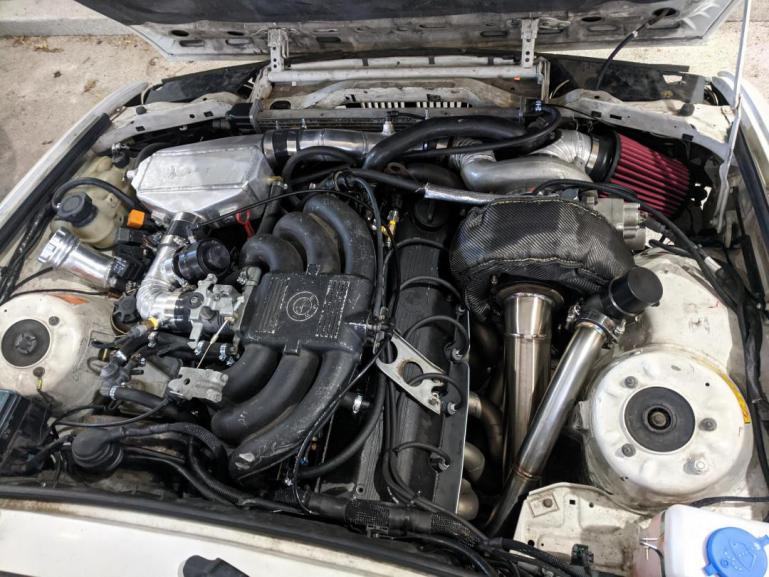
    Up and running, been very reliable and fun to drive. Using on-board compressed air to keep the wastegate shut during spoolup. Recently converted to later cooling system, tied wastegate into downpipe (no more screamer pipe), installed a new muffler, doing lots of cosmetic-type freshening up.


    Background, or version 1.0:
    Circa 2010, my dad and I decided to take on a project car. He'd had a shop in the early 80s building the snot out of M10 motors, turbocharging, 9k+ rpm, etc. He apparently had some very very fast tii's and 320i's back then, but he got out of it before I came around. He actively kept me away from wrenching when I grew up, but eventually he caved when I was home from college for a summer, and so we picked up someone else's unfinished (read: hardly started) e30 turbo project. 1987 325 sedan with an automatic (not even fancy enough to get the "e" on the emblem). Apline White over blue interior. Mostly Arizona, Texas, Florida car, odometer had stopped at 142000 miles. Paint wasn't in great shape, but otherwise it was in great shape with no rust or damage. It had hit 100k sometime around 1992, so who knows how many miles it actually accumulated. As far as I can tell, it was completely original save for an aftermarket head unit before the previous owner started their turbo project. For $2k, let's do it!

    Previous owner was a mechanic at a dealership, a "pro," technically. Said he had torn down the motor to check everything, and it all looked good so he put it back together with an 885 head. Came with some large diesel turbo, a 666Fab turbo adapter (using stock cast manifolds), a partially-built MS2 with V3.0 PCB, front-mount intercooler, a Getrag 260, 2.5" aluminum and 3" aluminized steel pipe/bends for fabbing charge piping and exhaust, and a whole mountain of odds and ends. Seemed like he got a good start, I just had to finish it up: turbo plumbing, swap the trans, wire the ECU, etc. Nothing too complicated.

    Engine was out of the car, so we decided to open it up to double check. It was nightmare inside: bearings were shot, bores were deeply scored, and some of the pistons clearly had hit valves. Not worth trying to salvage, and good thing we decided to double-check the PO's work:
    Click image for larger version  Name:	1397445291926.jpg Views:	0 Size:	55.7 KB ID:	9925003


    Click image for larger version  Name:	1397482972868.jpg Views:	0 Size:	107.5 KB ID:	9925004
    Click image for larger version  Name:	1397482772863.jpg Views:	0 Size:	76.0 KB ID:	9925005

    Note that this was the donor engine - the original short block was still in the car, so we took a look - it looked to be in great shape for its age, just needed some cleanup. After a lot of half-assed work on my part to get the car running over the summer with near-zero budget (would have been easier to start fresh, instead had to undo pretty much everything the PO did), including converting a 35-pin harness to a 55-pin connector to use a 55-pin adapter board, the car ran! The car's original engine cleaned up nice:


    Turns out the oil filter sandwich plate (used for turbo oil feed and oil pressure sensor) that came with the car was not a pass-through design (it required a run of hose from outlet to inlet), took a few heat cycles of giving the engine zero oil to realize the issue. Oops. Decided to just leave it together and run it til it popped. It ended up with a water-air intercooler, TD06-20G hybrid turbo, 3" turbo-back exhaust with a single cherry-bomb style muffler. Probably went 10k miles of beating the snot out of it on a crappy tune at ~11psi and a totally worn turbo, and eventually spun a rod bearing. Here's how it looked for its first iteration. I think it counted as a sleeper:
    Click image for larger version  Name:	IMG_1899.jpg Views:	75 Size:	70.1 KB ID:	9923161

    Click image for larger version  Name:	6280885531_56b941b8ca_b.jpg Views:	84 Size:	108.5 KB ID:	9923160

    Managed to score some Houndstooth coupe seats on the cheap from a junkyard. They also cleaned up nice with some replacement fabric:


    After blowing up the engine sometime in 2012, the car sat for two or three years waiting for a rebuild. That didn't happen til 2015. The goal for version 2.0 was to keep costs low, but not cut corners so much. Try to use as much stock, used, only paying for things that would significantly benefit reliability or performance: much more careful engine build, better cam, fresh valvetrain, but that was about it; also, do as much of the work as possible myself, with the limited tools I had, in my own garage.
    Last edited by mikey.antonakakis; 05-11-2022, 10:22 AM.

    #2
    Version 2.0, summer 2015:
    The goal was to mostly keep things the same, but don't cut corners on the engine build - buy all new valvetrain parts, any and all "while I'm in there" stuff (bearings, rings, hardware, etc) but keep the engine basically stock, save for HD rockers and an Enem Z45 turbo cam (280/280 at 11mm lift, and used a Nuke cam gear to set the cam timing to the manufacturer's spec). Stock head gasket with ARPs. Sourced a cheap 325i long block and another eta bottom end. Built the engine to factory specs on bearing clearances, ring gap, etc. Paid someone to resurface the head and do some very light port work, assembled myself. Engine went together very nicely, and other than having to pull the trans twice to figure out why the engine didn't want to spin with a wrench as soon as I tightened the trans bolts (forgot to remove the old pilot bearing! Didn't even try the starter, let alone try to run it, until I solved the problem, so no harm done).

    Kept everything else the same. Turbo was still shot (worn shaft, so rebuild kit didn't help), and left the boost around 11-12psi for this version, and she moved pretty good! Definitely much faster than before. Pretty handily outpaced a '02 Z28 with some bolt-on upgrades, could keep up with a lightly modded first-gen CTS-V.

    Carnage from the blown engine due to the damage caused by the original oil filter sandwich plate issue:
    Click image for larger version  Name:	10204072755874946.jpg Views:	0 Size:	72.3 KB ID:	9925009

    Clearancing pistons, ended up with 2-2.5mm clearance for the intake valve with the cam fully advanced:
    Click image for larger version  Name:	10204098673322866.jpg Views:	0 Size:	77.4 KB ID:	9925010

    Back together again:
    Click image for larger version  Name:	10204103146314688.jpg Views:	0 Size:	109.9 KB ID:	9925011
    Click image for larger version  Name:	10204100675292914.jpg Views:	0 Size:	103.7 KB ID:	9925012
    Click image for larger version  Name:	10204107368780247.jpg Views:	0 Size:	114.0 KB ID:	9925013


    Moved from Michigan to Colorado a few months after getting the car back together. Drove it for a couple months and decided to park it it in fall of 2015 due to the worn turbo. Was also experiencing a constant misfire, like it wasn't quite running on all cylinders. Had a pre-turbo exhaust leak too. Nothing too difficult to fix, but I'd picked up a VGT Holset (HE351VE) a year or so prior, so the intent was to slowly swap it in. For those not familiar, the turbo is 60mm in and out, so not too gigantic - pretty much perfect for my power goals - but due to the VGT mechanism, the turbine housing is enormous, and it also has a large electronic actuator hanging off the side. I knew I'd have to build an exhaust manifold from scratch, and figured I'd be doing all new intake and exhaust while I was at it. Also, the turbo is controlled via CAN bus, so I'd have to figure out how to set that up, too. A few years went by with very little progress as the car collected dust.
    Last edited by mikey.antonakakis; 05-27-2020, 06:44 AM.

    Comment


      #3
      Version 3.0, Winter 2019/20:
      And now the present-day build/rebuild details, where I finally get the Holset VGT turbo installed after sitting on it for 5+ years.

      The goal with this setup is to make good power on reasonable boost (1bar or so, hoping for 400whp). The cam helps a ton with that from other setups I've seen, and I am hoping the VGT gives a good bit more top-end power while not sacrificing much spool. Depending on who you ask, the nozzle area can change from a couple cm^2 to 25cm^2, and the compressor is pretty similar to HX40 I think... 60mm inducer and 60mm exducer, IIRC. So the compressor should be somewhat reasonably sized, and the turbine will get the turbo to spool about as aggressively as anyone could hope for with wheels this size; but most importantly to me, the turbine can get out of the way and improve VE at high RPM.

      The major challenge: the size of the housings and actuator. Here it is next to a Mistubishi 20g, the turbo I was running before. Definitely going to take a shoe-horn to get it in the car, and in the fit-up pics you can see some of the half-assed wiring and plumbing I had done bit-by-bit over the prior years:

      Click image for larger version  Name:	IMG_20191127_000612-1280x960.jpg Views:	389 Size:	73.8 KB ID:	9891823​


      No one makes an M20 manifold for this turbo, so I knew I'd have to make one. The most critical thing was figuring out how to get the turbo positioned and all the parts clocked in a way that it would actually fit in the engine bay with as much (or any) clearance as possible. I'm running solid aluminum engine mounts, which helps here because the engine won't be moving much. This also means the turbo position *relative to the exhaust ports/flange* is the critical thing.

      So I started by building a simple wooden mock-up of a manifold that would get the turbine flange in the right place relative to the head flanges. It took a few iterations, and I ended up with this position:
      Click image for larger version  Name:	IMG_20191022_202902_309.jpg Views:	282 Size:	95.3 KB ID:	9892258​

      A major design constraint I'd imposed on myself was to end up with equal length runners. The benefit of equal length could be debated, but it's what I wanted for sound, if anything. Also for the challenge of actually designing and building them 100% myself in my garage with limited tools (the cheapest Harbor Freight bandsaw you can find, an angle grinder, a cheap Chinese TIG machine, and barrels of elbow grease).
      Much, much work was done in CAD, and this was one of the earlier iterations:
      Click image for larger version  Name:	IMG_20191022_191832_01-1012x759.jpg Views:	276 Size:	60.1 KB ID:	9892261​

      It was tough to keep the CAD model stable, and I probably started clean-sheet three or four times between 2016 and 2019 (I'd spend a few nights on it for a few weeks, then abandon it for months). After quite a while, and quadruple-checking clearances, I ended up with the following 6-2-1 final design. All six primaries are equal length to within 0.5mm, and the secondaries the same. After considering options, I decided to add the external wastegate feed to the turbine housing, mostly due to packaging around the engine mount and oil/water lines for the turbo.
      Click image for larger version  Name:	PhotoPictureResizer_191215_171528550-1008x756.jpg Views:	272 Size:	65.9 KB ID:	9892262​

      The benefit of having the manifold fully designed in CAD was that there should, in theory, be no fiddling around with tube fitting. If I could manage to cut the weld elbows to the model specs, it should go together relatively easily with good fit-up. The major aspect of this that I couldn't control directly was the tolerances of the weld elbows... But I was hoping I could at least account and adjust for them. In regard to that, the way I actually measured and marked the cuts would be critical to getting the accuracy needed. I'm happy to share more details of that process if anyone is interested, but there were no fancy tools involved - Excel, pencil, paper, and cheap digital calipers.

      I decided to make the manifold from mild steel, biggest reasons being my lack of welding experience and skill (didn't want to end up cooking stainless, rendering it useless), ease of cutting, and lower thermal expansion (so maybe less likely to crack). In hindsight, I probably should have gone with stainless because just cleaning the black painted coating from the weld elbows added an enormous amount of work, and I needed to coat the mild steel, more than offsetting the cost savings.

      The good news was that the cuts came out fantastic, and while it was super fiddly getting the manifold tacked up, I didn't have to go back and adjust a single one of the pieces. Fit-up was excellent, with zero gap at most joints (as planned), and generally less than 1/16" gap on the worst joints (sch 40 pipe has >1/8" wall thickness, so no problem there). I also made a substantial jig from 3/8" and 1/2" plate to help mitigate warping. Flange placement relative to exhaust ports was taken from the CAD model, so that no matter what tolerances I had on the individual pieces, the flange placement only depended on the tolerance of my jig (I think I got it to within about 1mm of the target in any given direction).

      The jig will also come in handy if anyone else ever wants to fit this turbo to an e30...

      Click image for larger version  Name:	PhotoPictureResizer_191215_172821577-1008x756.jpg Views:	295 Size:	69.0 KB ID:	9892273​
      Click image for larger version  Name:	IMG_20191123_190216-1012x759.jpg Views:	289 Size:	63.5 KB ID:	9892274​
      Click image for larger version  Name:	IMG_20191124_132505-1012x759.jpg Views:	292 Size:	65.3 KB ID:	9892275​

      Click image for larger version  Name:	PhotoPictureResizer_191215_181954734-1008x756.jpg Views:	292 Size:	70.7 KB ID:	9892276​

      I ran the welds in a single pass, around 110-120 amps. Not always full penetration, but close to it, and in sch 40 that should be stout enough. I went through a lot of fill rod. Tube ends were beveled to about 35-40deg, with about 1/32" land. Other than a couple spots inside the valleys of the 3-1 collectors, I was pretty happy with how the welds came out for a beginner like myself. Managed to keep the heat in check, so if for some reason I decide to make another manifold at some point, I'm pretty confident I could do a good job with stainless and save myself a ridiculous amount of prep work (since the elbows and pipe won't have coatings, mill scale, and rust to deal with).

      The manifold got ceramic coated to help with heat, but mostly to prevent corrosion. Also, the placement in the engine bay is about as good of a compromise as I could manage in regards to heat. Just barely clears the body while installing, but has plenty of clearance once it's in place. The VGT actuator does not help with the overall packaging, as shown. That said, I didn't have to massage the bodywork at all to get things to fit (although I definitely couldn't fit the stock AC compressor...). Oil filter relocation kit also massively helped.

      Click image for larger version  Name:	IMG_20191125_192509~2.jpg Views:	292 Size:	47.7 KB ID:	9892278​

      Click image for larger version  Name:	IMG_20191127_001452-1012x759.jpg Views:	295 Size:	67.0 KB ID:	9892279​

      Click image for larger version  Name:	IMG_20191126_235517-1012x759.jpg Views:	296 Size:	67.9 KB ID:	9892280​
      Click image for larger version  Name:	IMG_20191126_235324-1012x759.jpg Views:	292 Size:	58.1 KB ID:	9892281​
      Click image for larger version  Name:	IMG_20191126_234829-1012x759.jpg Views:	291 Size:	60.3 KB ID:	9892282​


      The turbo, in its Dodge application, included a cast iron or steel elbow that bent about 70deg and expanded from about 3" diameter to 4". While it was a nice part, unfortunately the quick bend would only work for a hood or fender outlet, ha. This will be a daily driven street car, so that won't do. But since I had the elbow on hand, I cut it down to just the turbine-side flange and started the 3" stainless downpipe from there. I have very little stainless experience, so I practiced for a while before getting started. Used solar flux rather than back-purging, which worked pretty well! No sugaring, just some dusty flux reside that'll probably get blown out after the first drive. Here's my practice piece, about 2" at a time. I got better with each bead, especially once I decided to use the pulse feature of my TIG machine. The actual downpipe welds were a little inconsistent, but overall I'm happy with them.

      Click image for larger version  Name:	IMG_20191130_201051-1012x759.jpg Views:	42 Size:	61.7 KB ID:	9892286​
      Click image for larger version  Name:	PhotoPictureResizer_191215_184519366-1008x756.jpg Views:	42 Size:	117.1 KB ID:	9892287​
      Click image for larger version  Name:	PhotoPictureResizer_191215_184900515-1008x756.jpg Views:	42 Size:	63.4 KB ID:	9892289​
      Click image for larger version  Name:	IMG_20191211_213149-1012x759.jpg Views:	41 Size:	64.1 KB ID:	9892288​

      I'm generally not a fan of pie cuts, I think they're overdone for form/style over function (lots of extra work for no benefit in performance) but they do have their place - literally, like when there isn't space for a mandrel bend. Reluctantly, I ended up making almost all of the intake bends with pie cuts for that reason. It was my first time welding aluminum, but ended up being easier than I thought after a little practice getting machine settings dialed in.

      I had to cut off a good chunk of the compressor housing's outlet to make room for a bend to snake around the radiator hoses. The 60mm inducer is fed by a 4" inlet/air filter, so the indent I had to make on the compressor inlet elbow shouldn't hurt flow too much, and might help a little with the crank case venting (I'm running a catch can outlet to the turbo inlet, so maybe I'll end up with a slight pressure drop at that spot to help draw the vapors through).

      Mocked-up:

      Click image for larger version  Name:	IMG_20191207_000549-1012x759.jpg Views:	298 Size:	70.2 KB ID:	9892291​


      Air filter elbow, with the biggest filter I could reasonably fit behind the headlight. It's a dry filter, no messy filter oil to deal with:

      Click image for larger version  Name:	IMG_20191209_224416-1012x759.jpg Views:	289 Size:	60.5 KB ID:	9892292​

      Click image for larger version  Name:	IMG_20191209_235300-1012x759.jpg Views:	294 Size:	67.2 KB ID:	9892293​

      While I waited for the exhaust manifold to get ceramic coated, I decided to tackle a complete overhaul of the engine wiring harness. I was still using the Motronic-->Megasquirt adapater board from when I first got the car running in 2010, but since my car didn't use the 55-pin ECU, I made a real bird's nest of the harness conversion back then. Couple that with various gauges and features added over the years prior, and while it worked, it was embarrassing to look at and a nightmare to work with. Spent dozens of hours with the ETM, Megasquirt manuals, and doing some custom designs to add the VGT control, econometer functionality, better wideband electrical integration, etc. Made a full-on schematic in Solidworks Electrical and planned out every single wire, splice, and connection. More on that later.

      In the meantime, the manifold had come back from coating, so I was ready to get everything finalized and fully installed:

      ​
      Last edited by mikey.antonakakis; 05-27-2020, 06:46 AM.

      Comment


        #4
        The previous post is about as up-to-date as I had my other thread, and I've got quite a backlog of updates since then. I'll finish up the engine hardware build details first, then move on to the electronics - my project scope kind of snowballed, with things I had planned to put off til later in the year getting tackled this spring.

        As you may have noticed, there's no wastegate provision on the manifold - I eventually made the call to cut into the turbine housing. Although risky for someone with my lack of welding experience to try welding cast to stainless, worst case I'd need a new exhaust housing, and they are easy to find used, and cheap; so I went for it.

        Marked up for cutting, which was decidedly NOT a fun process, took about an hour of running a die grinder non-stop after I made the initial cut with a hole saw:

        Click image for larger version  Name:	IMG_20191207_110349.jpg Views:	92 Size:	65.1 KB ID:	9923188

        Tube notched:

        Click image for larger version  Name:	IMG_20191207_110538.jpg Views:	88 Size:	81.9 KB ID:	9923189

        After preheating the housing for a few hours, and using 309L filler, I CAREFULLY gave it a shot. Once I had a couple tacks on it, I tried making a light adjustment with some soft hammer taps, and broke a tack - or so I thought. The tack actually held just fine, but it pulled out a small chunk of cast iron with it! Thankfully nothing too big, but it was an eye-opener for how brittle the material was. After that though, the welding went smoothly, and I very slowly brought the temperature down over the course of several hours after I got it fully welded. I'm pretty happy with the placement - the wastegate will get fed a whole lot better than a lot of off-the-shelf manifolds, and it's fully upstream of the beginning of the opening in the housing that feeds the wheel. Also, it's in a pretty easy-to-access place, and uses v-bands, so working on it will be nice. Having done it a few times now, changing wastegate springs takes like 3 minutes and doesn't require lifting the car.

        Click image for larger version  Name:	IMG_20191207_215354.jpg Views:	90 Size:	80.7 KB ID:	9923190

        Click image for larger version  Name:	IMG_20191208_183146.jpg Views:	91 Size:	58.3 KB ID:	9923191
        Last edited by mikey.antonakakis; 05-13-2020, 10:49 AM.

        Comment


          #5
          The rest of the exhaust (all 3" 304 stainless) was a breeze, went together very quickly. First I finished up the downpipe:
          Click image for larger version

Name:	image_150942.jpg
Views:	1379
Size:	79.9 KB
ID:	9923200

          Click image for larger version  Name:	IMG_20191219_183828.jpg Views:	67 Size:	61.1 KB ID:	9923201


          Then moved on to the rest of the exhaust:

          Click image for larger version  Name:	IMG_20200324_171927.jpg Views:	68 Size:	76.4 KB ID:	9923203

          Click image for larger version  Name:	IMG_20200324_155634.jpg Views:	68 Size:	79.3 KB ID:	9923204
          Last edited by mikey.antonakakis; 05-12-2020, 10:34 AM.

          Comment


            #6
            And then got the exhaust finished up and the engine bay all buttoned up, including turbo oil train, oil feed, water lines, remote oil filter install and associated hoses, new wiring harness (more on that later), late-model coolant reservoir, relocated washer reservoir, and on and on. Muffler was $15 brand new on Amazon, it's stainless, but I accidentally ordered a black powder coated unit, oh well. It's a single-chamber, no-fiberglass, mostly straight-through guy. Just an couple simple baffles in there. The objective for sound, with the equal-length manifold especially, was to go for high-pitched screamer. So definitely no fiberglass anywhere. I might end up adding a helmoltz resonator or two before the muffler, but this is the state of things at the moment.


            Click image for larger version

Name:	IMG_20200323_220700.jpg
Views:	1265
Size:	73.6 KB
ID:	9923211
            Click image for larger version

Name:	IMG_20200324_182120.jpg
Views:	1286
Size:	71.4 KB
ID:	9923213
            Click image for larger version

Name:	IMG_20200326_183532.jpg
Views:	2046
Size:	88.4 KB
ID:	9923214

            Oh, and I found some pictures of the finished manifold before coating:

            Click image for larger version

Name:	IMG_20200121_160744.jpg
Views:	1282
Size:	72.9 KB
ID:	9923212
            Click image for larger version

Name:	IMG_20200121_160722.jpg
Views:	1292
Size:	72.9 KB
ID:	9923210

            Comment


              #7
              And here's how she looked once I got her all back together. The exhaust outlet the only visible indicator that there's something not-stock about her. Wastegate dump ends just behind the front subframe, but I may extend it to exit just behind the front wheel.

              Click image for larger version  Name:	IMG_20200325_190249.jpg Views:	85 Size:	77.4 KB ID:	9923216
              Click image for larger version

Name:	image_151280.jpg
Views:	1205
Size:	75.3 KB
ID:	9925294

              Click image for larger version  Name:	IMG_20200512_160024.jpg Views:	0 Size:	69.6 KB ID:	9925295
              Last edited by mikey.antonakakis; 05-13-2020, 10:57 AM.

              Comment


                #8
                Before going on to electronics details, a screenshot from last night's quick shakedown session trying out a stiffer wastegate spring, GoPro pointed at exhaust outlet:
                Click image for larger version  Name:	GH010014_1589255713761.jpg Views:	0 Size:	26.2 KB ID:	9924909

                The state of the wiring up to this latest rebuild left something to be desired. Yes, it worked, quite reliably somehow. But, it was a real headache to work with, what with the converter Motronic 1.0 to 1.3 harness, adapter board, and various circuits added over the years. I decided to basically start the engine harness from scratch (well, starting with a DIYAutoTune flying lead harness, technically...). Here's how it used to look in the glovebox, and how the harness + adapter board looked once it got pulled from the car. Yikes, what was college-aged me thinking??

                Click image for larger version  Name:	IMG_20200118_173739.jpg Views:	26 Size:	82.5 KB ID:	9925021
                Click image for larger version  Name:	IMG_20200120_075418.jpg Views:	26 Size:	78.9 KB ID:	9925022

                I ended up buying a hard copy of the ETM, and used Solidworks Electrical to design the new harness to be as clean and easy to install/remove from the car as possible. It's pretty cool software - I didn't end up using all of its features, but it essentially is a database that links the components "smartly" - somewhere it keeps track of all connections, splices, components, etc. I mostly used it for my own sanity; even though the schematic looks pretty complicated, the color-coded wires help immensely (which btw have all of the details stored, e.g. 0.75mm^2 Green with White Stripe). I'm no electrical engineer, but this got the job done, especially since you mostly build one of these wire-by-wire anyway.

                First, the line diagram, which is more of a high-level overview of what's included and how it's laid out. I didn't complete it fully, but it's not really the driving force behind the design:
                Click image for larger version  Name:	line_diagram.PNG Views:	26 Size:	354.9 KB ID:	9925024

                The real design details are in the schematic, including pin numbers/names, wire details, etc:
                Click image for larger version  Name:	schematic.PNG Views:	26 Size:	264.7 KB ID:	9925023
                Last edited by mikey.antonakakis; 05-13-2020, 11:18 AM.

                Comment


                  #9
                  [Previous posts were updated with some photos and additional info to get them up-to-date, and because I found some old photos I thought I'd lost.]


                  The overall goal with the wiring was to, as cleanly as possible, merge only the needed aspects of the stock engine harness with the Megasquirt flying lead harness, and adding in all additional features as needed. And, there were quite a few additional features... more on that soon.

                  I reused some of the stock connectors where it made sense, like C101 for integration to the body harness, C104 for the connections to the dash, sensor connectors if they weren't pigtails (e.g. coolant temp sensor). I removed any non-used sensors, connectors, wires, etc. - for example, the coolant temperature switches for the fan control, which would be handled by Megasquirt. Only what was needed to make all of my desired features work, and nothing more.

                  The process started by doing some reverse engineering/deconstruction of the stock engine harness to understand what was there, how it compared to the ETM, and if it was really needed or not. I gradually removed wires one by one if they weren't needed to get the stock harness down to the bare minimum. I'd estimate I kept roughly 30% of the stock wiring. It was a sticky process, wore my fingerprints away:
                  Click image for larger version  Name:	IMG_20200219_174204.jpg Views:	86 Size:	69.2 KB ID:	9925033

                  Throughout that reverse engineering process, I was working on the new harness design (final iteration shown in previous post). Once I was confident everything was included in the design, and I was happy with all the wire sizes, rough routing, etc., I started the splicing process. Not super fun, and took far too long - but worth it in the end, I think. I also tooled up a bit - everything crimped this time around. Open-barrel splice connectors for any and all splices, Deutsch DT and DTM connectors, new crimping tools (none name brand, but they worked really well for the most part). Dual-wall adhesive heat shrink everywhere, and braided nylon sleeving to wrap it all up. It was amazing how much brain drain happened from just trying to assemble things in the right order... definitely a different way of thinking about things than I'm used to.

                  Click image for larger version  Name:	IMG_20200215_112558.jpg Views:	84 Size:	84.6 KB ID:	9925034


                  Some of the sleeving had to go on before all the wires were run, due to existing connectors - generally, it got built from the middle of the harness out. Partially complete:

                  Click image for larger version  Name:	IMG_20200217_140048.jpg Views:	84 Size:	81.2 KB ID:	9925035


                  With the DT/DTM connectors and the sleeving, I'm happy with how all the terminations ended up. For example, the branch with a swapped throttle position sensor connector (from an e34, I think?), stock idle control valve connector, and GM-style intake air temperature connector:
                  Click image for larger version  Name:	IMG_20200221_000941.jpg Views:	84 Size:	73.8 KB ID:	9925036

                  And the pretty much finished product, with just the turbo connections to finish up I needed to get it in the car to finalize that branch. Oh yeah, I ran the Megasquirt's vacuum line through the harness as well for a cleaner install using the stock firewall grommet:
                  Click image for larger version  Name:	IMG_20200223_173355.jpg Views:	84 Size:	69.4 KB ID:	9925037
                  Last edited by mikey.antonakakis; 05-13-2020, 11:22 AM.

                  Comment


                    #10
                    I mentioned before that my project scope creeped a whole lot for this iteration - originally I wanted the car running with the new turbo by New Year's Day, doing the bare minimum to get there (exhaust manifold, intake plumbing, downpipe, and maybe the rest of the exhaust, reusing everything else as it existed before). I didn't quite make it, and the urgency I felt decreased, so I decided to do it "right" from the get-go, and build things the way I ultimately wanted them to be (at least everything related to getting the car running with the features I wanted to add).

                    The VGT turbo was a big driver of the feature-creep here. Originally, I planned to use an Arduino to simply read the PWM boost solenoid signal as output by the Megasquirt, convert that to vane position, and send the position with a CAN transceiver - nothing too complicated. Then I started digging into the Megasquirt features a bit more, and realized it could broadcast parameters over CAN, and since I'd be using CAN no matter what, I could read the boost duty over CAN instead of directly from the Megasquirt's boost solenoid output. And if I could read boost duty over CAN, it would be mostly copy-paste to read any other parameter the MS broadcasts.

                    Here's some of the initial simple VGT bench testing, with the turbo responding to changes in boost vs boost demand as I simulate boost with a syringe hooked up to the MAP sensor:


                    Then I realized Megasquirt can take CAN data as additional sensor inputs - and since I am quite limited on analog sensors by Megasquirt 2, this could be a huge help for logging things like fuel pressure, oil pressure, turbo speed, etc. Unfortunately, implementing this wasn't super well-documented. Megasquirt CAN data broadcasting is pretty simple - there are a few parameters sent in a given message ID, so check the ID to see which parameters are in the message, then extract them. But to send data back to Megasquirt, a request/response protocol is used. Megasquirt requests data with a pretty highly-encoded data structure: the message ID contains information about which data is being requested, who is requesting it, who it's being requested from, how much is being requested... the request message data buffer contains other info as well, all of which has to be interpreted to understand what exactly Megasquirt is asking for, and how it wants the response to be structured. Once you interpret this, you have to build a response in exactly the way Megasquirt requests - and if you succeed, Megasquirt will take the data you sent and store it in the 8 virtual GPIO channels it has, at which point you can set up functions in TunerStudio to interpret those inputs.

                    I'm definitely not a developer, but I figured since I'd have to do the work anyway, I'd build an Arduino library that anyone could use to do the same thing. It contains ALL of the broadcast parameters than can be sent by a MS2 or MS3, and methods for receiving, interpreting, and responding to Megasquirt requests for CAN data.
                    Last edited by mikey.antonakakis; 05-13-2020, 11:58 AM.

                    Comment


                      #11
                      Onwards to the details of my build in this regard; here's the basic structure of how the CAN communication flows between Megasquirt, my microcontroller, and the turbo:
                      Megasquirt <--> Microcontroller --> turbo

                      Megasquirt broadcasts data, which is read by the microcontroller. Microcontroller processes the data to determine the VGT position, and sends the command to the turbo. In short - if Megasquirt says we need more boost, the microcontroller determines how badly we need more boost, and closes the vanes accordingly. Once we don't need anymore boost, the vanes open fully to allow the engine to breath as much as possible.
                      In addition, Megasquirt requests sensor data from the microcontroller, and microcontroller responds accordingly the request, allowing the Megasquirt to log additional data channels.

                      One of the things that bothered me with previous iterations of the car was the messiness required to display info while I drive - it's tough to really cleanly install gauges, and if you ever want to add additional gauges, it's tough to not make a mess of the splices required. Since I built up the ability to get dozens of channels of data with just a couple wires using CAN, I figured I'd build a solution that takes advantage of it: a multi-function display that can display any info I'm interested it. Expandability is the key feature here: add some code, and you have another gauge. No worrying about how to mount it, where to splice, how to make the wiring clean.

                      So, as I considered all of these features, I ended up with the following setup:
                      • Standard MS sensors (IAT, TPS, CLT, Crank position, Wideband) wired as usual for MS setups, to the DB37
                      • Standard MS outputs similarly (fuel pump relay, wasted spark outputs, injector outputs, PWM idle control)
                      • High-voltage flyback tach circuit added to the regular MS tach output, since the stock tach was triggered by the coil from the factory
                      • CAN wired as normal for MS
                      • Fan control using a relay trigger circuit (using the stock high-speed fan relay/wiring)
                      • Intercooler pump control using a relay trigger circuit (using the stock low-speed fan relay/wiring)
                      • Fuel pressure sent to the microcontroller (Teensy 4.0) using an analog input
                      • Oil pressure sent the same way
                      • Circuit built using a VR encoder IC (MAX9924) to read turbo speed, since HE351VE includes a speed sensor
                      • Fuel and oil pressure, turbo speed, and turbo vane position (technically, nozzle area in cm^2) sent to Megasquirt for datalogging
                      • Stock econometer functionality: microcontroller reads injector pulse width from CAN, converts to duty cycle based on engine speed, scales to account for the bigger injectors I'm running, sends it as a PWM output with PWM frequency matched to engine speed, and scaled to a 12V signal with a transistor circuit
                      • Turbo VGT actuator power controlled by an output on the microcontroller, with corresponding booster circuit on the microcontroller output to power the relay
                      • Stock OBC (multi-function clock in my case) replaced with a 2.8" touchscreen display with a custom housing and bezel to hold all of the microcontroller circuitry


                      I'll have to get a better video of it at some point - the turbo gauge is pretty fun, shows turbo speed and turbo size as well as boost pressure. Logging that data is really helpful for the VGT tuning.

                      Comment


                        #12
                        And here's a quick second gear pull from last night, around 9psi - too much wind noise, was trying to get some sound reflecting under an overpass:

                        Comment


                          #13
                          Good lord, nice work there!
                          sigpic

                          Comment


                            #14
                            Thanks!

                            Here's a third gear pull from last night, maybe a little uphill. Note the turbosize and turbospeed parameters in the datalog. Spool might not seem too great for a 60mm/60mm turbo for hitting the throttle at 4000rpm, but there's a big caveat:
                            When the vanes close at mid-range RPM, there's enough exhaust pressure to force open the wastegate, even with the stiffest spring for my wastegate (~9.5psi up here at 6000', would be ~12.5psi at sea level; it's a JGS 40mm). Going by my ears (wastegate dumps under passenger footwell), the wastegate is basically wide open between 3-6psi above atmospheric, at which point the vanes start to open and the wastegate shuts again until I hit peak boost (around 12.5psi above atmospheric). I can't really hear it when I first hit the throttle, but it might be open then, too. Of course an open gate should give much slower spool.

                            I don't want to run more than about 15psi (210kPa absolute) any time soon, and JGS doesn't sell a stiffer spring for my wastegate anyway. Conventional electronic boost control with a solenoid wouldn't help too much, since it mostly isn't boost that's opening the gate, it's exhaust manifold pressure. So to fix it I either have to pressurize the top of the wastegate (CO2?), or source a stiffer spring, or make the VGT less aggressive. I don't want to go with the last option, I don't have any apparent surge and the current settings don't hurt my VE very much during spool (not much noticeable difference in AFR in this datalog between fully open and closed vanes).

                            Table in bottom right shows full spool parameters: ~1.5s to hit target boost at 4000rpm. Minimum turbine nozzle size 7.5cm^2, not too aggressive. Vanes stay fully closed until I'm 65% of the way to my target boost (from atmospheric, I run a baro sensor too; in this case with baro of 80kPa and boost target of 165kPa, the vanes stay fully closed until ~135kPa).

                            Click image for larger version  Name:	3rd_gear_2020-05-12.png Views:	0 Size:	136.8 KB ID:	9925250


                            Same log, but highlighting the time period when the wastegate was opening prematurely. You can see the slope decreases for both MAP and turbo speed in a similar way to poorly-tuned electronic boost control:

                            Click image for larger version  Name:	3rd_gear_wg_blown_open_2020-05-12.png Views:	0 Size:	134.9 KB ID:	9925252


                            And finally, same datalog but highlighting the full boost region. With my 2.93 diff, this window corresponds to 75-102mph in 3.5 seconds (gearing checked against GPS speed), not too bad for 167kPa?

                            Click image for larger version  Name:	3rd_gear_full-boost_2020-05-12.png Views:	0 Size:	135.0 KB ID:	9925251

                            Comment


                              #15
                              That multifunction display is really neat. I love that, just have very little coding skill so I wouldn't know how to implement it.

                              What type of controller are you using with the VNT? Since the system is continuously variable, is it being tuned to operate in open loop or will it be closed loop? Since the goal is to maximize mass flow during times of high power demand, measurable simply in a dyno environment as increased torque over the duration of a full throttle pull from low engine rpm vs a baseline pull with the nozzle fully open, but difficult to measure in practice during street tuning or with limited dyno time, how are you gauging turbine efficiency to determine whether the nozzle needs to be opened or closed further at any point? Correct me if I'm wrong, but are its goals not maximizing rate of increase of mass during boost onset and mass flow for a given engine speed at lower engine speeds, not maximizing boost pressure itself? This being a device which has the goal of optimizing turbocharger performance, you could conceivably see an increase in boost pressure without in associated increase in torque at a given engine speed by restricting the exhaust flow too much while chasing a boost number, reducing flow through the engine and increasing work done on the exhaust gasses during the exhaust stroke, akin to just having an undersized turbine housing. Are you monitoring exhaust manifold pressure or EGT while tuning the VNT controller?

                              Very cool project, probably the most interesting ongoing project on this forum at this time since it is adding a significant layer of complexity, using something that is so seldom even thought of in the hobby.

                              IG @turbovarg
                              '91 318is, M20 turbo
                              [CoTM: 4-18]
                              '94 525iT slicktop, M50B30 + S362SX-E, 600WHP DD or bust
                              - updated 1-26

                              Comment

                              Working...
                              X