

Can you post a picture of the damper on the front of the crank, and the back of the intake cam sprocket? I have a couple of ideas...
-
-
The aluminium is super nice and all, but isn't there a groove for the other gasket missing? Are you going to just silicone/rtv it?Comment
-
no front 60-2 wheel
Here's a picture of the front of the engine. My understanding is that the M52/S52 motors have Siemens ECU's with 60-2 toothed wheels in both the rear and front of the engines, they use Hall sensors in the rear but the front wheel is unused, kinda like the vestigal legs in snakes.
OBD1 conversions will just add the VR sensor to the bung in the front becuase the wheel is already there.
The M54 has evolved to comletely shed the front sensor wheel and the mounting bung for the VR sensor is now gone. The front timing cover was completely changed to accomodate the new cooling scheme and dual VANOS. All I have to work with is the crankshaft mounted sensor wheel in the rear.
I have plently of stuff in the mail and some projects brewing in my lab to overcome that. More to follow.
Also note that I can't even remove the A/C pulley. It's part of the main pulley/dampner.
As far as the Zionsville waterpump, it uses the same gasket as the M50 waterpump.Attached FilesComment
-
-
sensor lab
I got a bunch of stuff in the mail today so was finally able to fire up my sensor lab. It's based on the BMW factory tool, the standard signal wheel on a bench grinder setup.
I have the M54 Hall crank position sender , an M50 sender, an M20 one and a few aftermarket units. A mini history of BMW sensors!
My quick quick look at it shows that the Hall sender produces a solid 5V square wave signal at almost any wheel speed down to zero. That's the beauty of active electronics.
Comparing the aftermarket "aerospace" quality 3/8" sender to the M50 Bosch sender shows that the Bosch one clearly rocks. It produces at least 5 times the signal magnitude and generates a 10 v peak-to-peak signal all the way down to about 80 rpm on the wheel and that's with a generous air gap.
The 3/8" sender doesn't produce that kind of voltage until a few hundred rpm. It does make a nice, clean signal but a car will never start if it needs to be cranked to a few hundred rpm!
I honestly don't know what the threshold level is but it's not even close to the Bosch unless I got the air gap down to a few thousandths.
Next up... I have a charge pump waiting in the wings....Attached FilesComment
-
-
lol, oscilloscope + bench grinder = shadetree
Still, awesome work though. Way to be resourceful!!Comment
-
the depth of teeth on the inside crank gear is definetly smaller. not sure if that would effect how the VR works. But my vote would be to hack up the stock bosch VR sensor to make it fit and seal inside the block.
600hp beastComment
-
Yep, I didn't mention that but smaller depth PLUS smaller diameter, which reduces the linear velocity that VR needs to generate the signal spells trouble for using a VR in the rear.
I haven't whipped out the charge pump yet but my next tactic will be to turn the half-wave Hall signal into a full-wave signal. It's the zero crossing point that the ECU is looking for.
I could also tap the rear hole for a 3/4 threaded VR and I'm sure that would work, too! Larger diameter=more sensitivity.Comment
-
Charge pump success?
Things are looking up for using the Hall sensor and doing some signal conditioning to make it look like a VR signal. I got the charge pump working and made it change the original Hall signal into a full-blown +12v to -12v signal.
I've got a VR sensor on channel 1 here and a Hall senor on channel 2. The sensors are exactly 3 teeth apart, with the VR sensor lagging the Hall sensor.
This capture was at about 100 rpm, you can see the phase of the two signals are pretty close as is the voltage. The missing tooth crosses the Hall and then the VR sensors, the waveforms look a little different here. The Hall sensor reads the missing tooth literally and the VR sensor has a zero crossing half way through.
I'm not sure how the ECU decodes the VR signal, but I'm thinking it looks for the zero crossing is it goes positive again to start the next revolution, in which case it's good.
Next step is to solder up the package and install the Hall sensor in my running M50. It's exactly 2 chips, 2 capacitors and a potentiometer. That's it!Attached FilesComment
-
-
Wiring Harness
So the Hall sender conversion is done. I installed the completed circuit in my M50 with a Hall sensor and verified that it works today. It is completely transparent to me and I forgot that I had on the drive home until some hot chics asked me at a stoplight "is that a Hall sensor in your M50" and I sheepishly replied "yes. yes it is." I know this part of the conversion will work.
On to the wiring harness.
I have the stock M54 harness and an e34 harness. I will need to use some of each and will end up with a mash-up harness. From the M54, since I'm using the M54 manifold, I will need to use the fuel injector and coil harness. The coil harness is already completely seperate and the fuel injector harness I will need to cut off. I hope the wire colors are the same! I will remove and completely replace the e34 version of those. All the sensors look the same as the M50 so the rest of the e34 harness is fine.
Gone will be the M54 DISA connection, fly-by-wire throttle body and quad Oxy sensors.
I have a red label 413 that I'll put an M3 chip in (thanks Doug!)
I will also remove the e34 tranny plug. Shame on you that have kept it, I plan on never having a transvestite in my car (that I know of). Anyone know what the two extra plugs by the ECU connection are? I've got 3 relays and 2 unidentified auxilliary-type plugs. An ID would be appreciated (lower-left portion of photo, one is black and one is white).
In fact, I would appreciate any notes on sensor connection wire colors to save me some hours of ETK madness.
On deck: install fuel pressure regulator.Attached FilesComment
-
-
Maybe you covered it but I still dont get how youre going to run a dual vanos motor on a DME that can only run single vanos.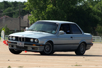
As time went on, the factory developed the car each year, making it faster, more comfortable, and capable of handling at higher speeds.
You don’t want this. You want the trickiest, most dangerous, oldest model you can find. Only then can you prove to the world that you’re a man.Comment
-
Instead of changing to the M52 injector and coil wiring stuff, I would get rid of the e34 injector harness box and replace it with 6 individual injector connectors and leave the coil connectors the same. I would use the stock OBDII e36 coils (I would think they would fit) and the e34 coil harness.Comment
-
You're right, the 413 can only run the intake. I will only have the intake VANOS and leave the exhaust VANOS disconnected. Intake will be an on/off affair. Motor should end up looking like an S50 to the ECU. I could be wrong. There's a difference between getting it running and getting it tuned and running well, I hope to get it running first. I've read in a few places that 90% of the exhaust VANOS function is for internal EGR and for fast cat warmup. Maybe 10% is for power.
Yeah, I suppose that's another way of doing it. The M54 fuel wiring box also has water temp, air temp and intake VANOS connectors nicely integrated into it. Is that the way the M52 is, as well? I don't know if it's the same as M52 or not.Comment
-
Dry fire!
I've finished mashing the two harnesses together. I used most of the e34 harness and spliced in the M54 injector and coil sections, which look nice on the motor. In addition, the m54 runs the coolant temp sensor, intake temp sensor and intake VANOS actuator through the injector wiring box so I moved the e34 ones there, as well. Almost all the sensors match the plugs exactly, the only exception being that the cam sender plug is male and so is the engine pigtail. I guess I'll switch to an M50 sender.
The cool part is that I got the motor to dry fire. That is, I connected the ECU, connected power and the ignition voltage, generated a crank signal and watched the sparkplugs go off. It's pretty cool. I'll verify a few more little things like injector signals and the fuel pump relay.
To do: where is my e30 temp sender going to go? The M54 has a mounting bung on the inlet side of the thermostat that was meant to help control the cooling fan. I could mount it there and read inlet water temps or find a place on the head.
Edit: I should add that I've noticed it seems to run in wasted spark mode without the cam sensor. That is, plugs 1 & 6 are firing simultaneously, not sequentially.Last edited by hoveringuy; 10-26-2008, 07:55 AM.Comment

Comment