M42 ECU Conversion: Link G4X / E36X

Collapse
X
 
  • Time
  • Show
Clear All
new posts

  • bmwman91
    replied
    Today I started in on some CAD for adapting the Bosch pressure/temperature sensors to fit on the engine. The one for the oil will go in the oil filter housing where the stock pressure switch was. Since the existing hole is M12x1.5, and the sensor is M10x1, I need to drill it out a bit larger and install a thread repair sleeve. It is also a bit longer than I'd like since (ideally) the thermistor tip in the sensor would be in the actual flow of oil. I can't trim it enough to get the sensor that far in, but I can certainly get it a bit closer. I got out the calipers and made some measurements with which I modeled the threaded boss area. The main limiting factor for pushing the sensor further in is the big open cavity inside where the oil bypass valve is (the one that should never open unless somehow the filter gets totally clogged).


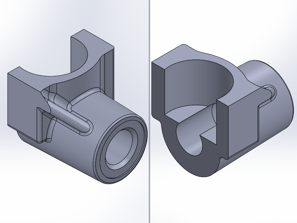
    So with a little trimming that can all be done pretty easily on a manual mill, here's how the sensor will end up fitting in there.


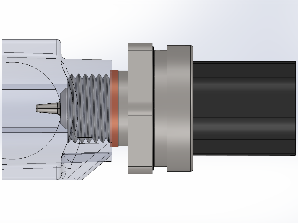
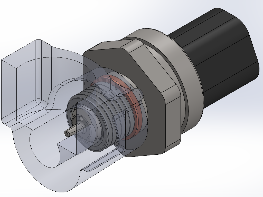
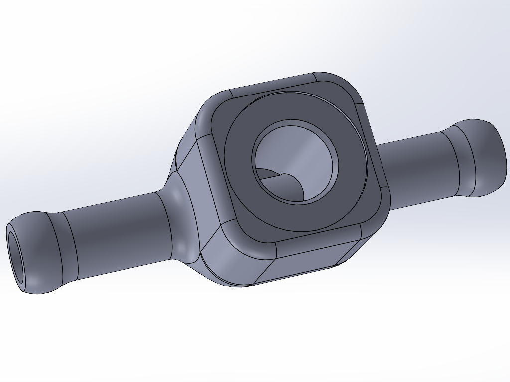
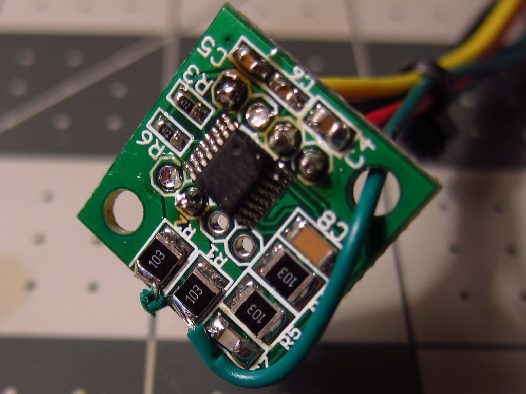
    For the fuel sensor, I am planning to have a little inline tee fitting CNC machined from some 7075 aluminum rectangular bar stock I have laying around. This will install into the 8mm ID hose that feeds fuel into the rail, as close to the rail as I can get it. I'd expect the fuel to heat up minimally overall since it flows at a fairly high rate and has a lot of metal tubing to dump heat from between the front & rear of the car, and it probably does not spend enough time in the rail to significantly heat up much more after the sensor, so I figure I will get a decent reading of it like this. The other option was to get a spare fuel rail and have a friend TIG a little threaded boss onto it, but that seems very unnecessary, and would be a pain in the butt to access if I needed to replace the sensor.


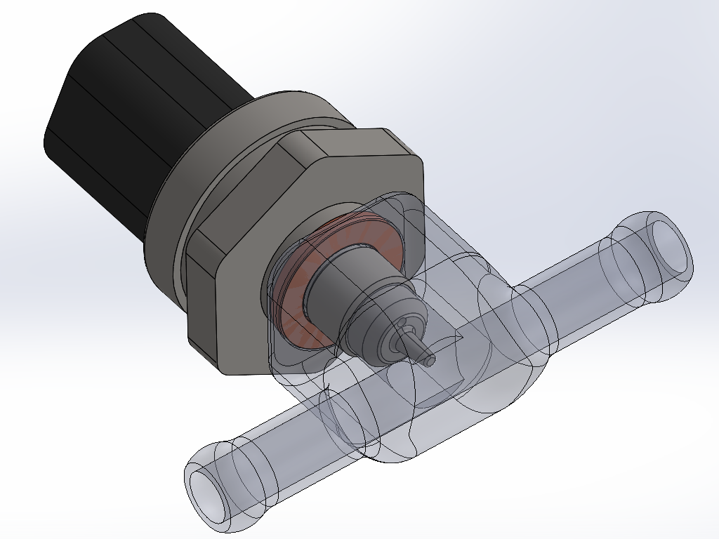
    The other open items I have are to figure out where & how to mount the M50 ICV, and how to mount the MAP+IAT sensor. I'd like to fit the ICV in approximately the same location as the original, but it is pretty tight and will likely require even more custom machining. The other option is to mount it vertically in the open(ish) area behind the intake boot and a little to the left of the intake manifold. For the MAP+IAT, I am thinking I am going to mount it on the rear-most sloped face on the top of the intake manifold since that is the only spot I where I am confident that it'll clear the hood insulation. Maybe I will try sticking some foam blocks on the top flat part to see if I can clear the insulation closer to the middle, but it seems iffy. Either way, it needs 9~10mm of material thickness to get a seal with the o-ring it uses, so I will need to machine a little mount plate or flanged sleeve or something.

    Leave a comment:


  • bmwman91
    replied
    Here's a picture of what remains of the original harness that will be used going forward...


    ...and here is what is being discarded. Well, most of it. I am keeping the relay sockets, which were removed for cleaning & wire re-routing.


    Part of me was tempted to just build a whole new harness from scratch, but that would have ended up being a few hundred dollars in needless extra cost. The stock wire has PVC insulation as far as I can tell, which is not amazing or anything, but it is perfectly fine for an engine harness. The new wire I have ordered all has Tefzel (ETFE) insulation, which is considerably sturdier while also allowing for thinner wall thickness. Smaller overall wire diameter makes for slightly easier routing, and since I am going to be increasing the number of wires coming from the ECU plug by 28, I want to have some extra help in being able to fit them all out of there!

    Leave a comment:


  • bmwman91
    replied
    I spent a number of hours yesterday tearing-down my spare harness and cleaning it. It took nearly a pint of 99% isopropyl alcohol to get the tape residue and grime off of all of the wires. If you have ever worked on one of these old harnesses, you know the pain of dealing with that nasty tape adhesive! It was a task that I had not been looking forward to one bit, since I had done it once before at the start of 2020 when I cleaned up and modded the harness that is in the car now (integrated MAF & WBO2 wiring, properly routed/trimmed ignition coil leads: all for the stock ECU). This time was a little easier since I COMPLETELY took the harness apart...I completely de-pinned the ECU plug & relay sockets, chopped off all of the JPT plugs for the various sensors & actuators and permanently removed all but 5 terminals from the diagnostic plug (leaving only the ones needed for SI light reset & the tach signal). Most of the wire sheaths were removed, with only the little pieces near C101 and the diagnostic plug are going to remain. The sheaths on the main power & ground wires will be removed when I chop apart the splices, since I need to add / change wires in those bundles. My pile of "scrap" harness wires is as large as what remains! I took some pictures, but they are at home on my camera, so I'll see about posting some of those up later today.

    As of last Thursday, my big order for new wire, parallel splices, heat shrink tubing & new PVC sheathing have shipped, so I should have a big pile of new stuff to start roughing-in this week. A big beef I have had with the harnesses is that a lot of wires are all tangled & twisted. This is why I completely took the harness apart...all wires will be bundled a LOT more neatly, with no needless weaving/twisting, no loop-backs and more than a dozen splices completely removed. Every signal / analog wire that ran from the ECU to the wire box has been removed since they all had little splices on them in the wire box. This was done to make harness assembly easier...pig-tails from each connector were made, routed in to the box and then joined to the long wire from the ECU, rather than running a single wire and having to assemble the connectors onto the ends at the end. Also, I chopped off all of the connectors (except for the crank & cam position sensor ones, those are fine the way they are) because they were heat-staked to prevent terminal removal. You can actually release the terminals if you knock out the little staked sections with a hobby knife, but that leaves openings in them right at the edge of the boot. Maybe I will take some pictures of this, just in case anyone is interested.

    Other than roughing-in the wires, not much else will be done until I can yank out the existing harness and put this disassembled one into the car. I am going to size & route all of the new wires in-place before installing any connectors, tape or other fixings. A big pet peeve I have is that all of these are "too long" inside the car where the main loom runs to the ECU. I'd guesstimate that they are close to 10cm too long, requiring a bunch of bending & brute force to cram the wires out of the way to get the ECU plug into place. As it is, 75% of the wires going to/from the ECU have been removed and new wires+terminals have to be installed, so I will chop the terminals off of the remaining wires and cut them to a proper length once I have it all dry-fitted in the car.

    More to come.....

    Leave a comment:


  • bmwman91
    replied
    I have been been a little quiet in here lately, but I have been working on this more. Specifically, I have been drawing up the fully detailed wiring diagram for the new harness and a pin-board to get length estimates with. Although I do not plan to make a physical pin-board since enough of the original harness will remain intact to keep things properly sized, I will probably install it into the chassis after removing all of the tape and cleaning it so that I can route all of the new stuff in-place to get the lengths exactly right. The pin-board drawing is more for determining quantities of wire to buy.

    PDF links are the full-size drawings of the "thumbnail" images.

    For the pin-board drawing, I started out by measuring out everything on a 100% stock harness. Dimensions probably vary a bit since these things are all 30 years old and varying amounts of tugging/abuse have been applied, but everything is likely within 1cm of where it should be.


    OEM E30 M42 Harness Dimensions


    I have already posted this elsewhere, but here are the OEM E30 M42 wiring diagram and the modified one I am using currently with my MAF conversion & WBO2 on stock Motronic, in full color:
    http://www.e30tuner.com/assist/m42wi..._318iS_OEM.pdf
    http://www.e30tuner.com/assist/m42wi...ess_MM2100.pdf


    Anyway, it took a fair bit of work to figure out exactly how I wanted to add & route all of the new stuff for the Link ECU. A primary goal was to have a single wire loom coming from the ECU, which means that I will need to void my warranty and solder some jumper wires inside the thing from the "extra" I/O pins on the G4X ECU and unused pins on the main 88 pin connector. Also, while it has a built-in MAP sensor, I do not want to have a vacuum line running through the firewall (both from a SMOG/visual standpoint, and just for cleanliness). So that means that I will be using a Bosch MAP+IAT sensor, mounted directly in the plenum of the intake manifold.

    The other thing I had to think about a lot was the fuel injector wiring. The stock setup has a pluggable sub-harness for the injectors. The ONLY reason I can see for this is to make engine removal/installation simpler at the factory. Removing the injector harness requires removal of the upper intake manifold. In my experience, the M42 is much more easily removed/installed without the upper manifold anyway, and (*FINGERS CROSSED*) I don't anticipate removing the engine again anytime soon. With the "mess under the intake" mod, the upper manifold can be removed without messing with the TB, and is a 10 minute job. So, with that said, the fuel injector wiring will run through the little side-port in the rubber umbilical that the ICV wires previously exited from. This is the most direct route for the injectors. The ICV, MAP & fuel P&T sensor wiring will exit where the fuel injector connector used to be (with a 3D printed PEEK filler/adapter for the grommet). It just makes more sense that way.

    New stuff which I will be routing through the wire box under the intake manifold:
    - Oil pressure + temperature (mounted in oil filter housing where the pressure switch was, with some custom machining to adapt the existing M12x1.5 hole to take the M10x1 sensor)
    - Fuel pressure + temperature (will machine an inline tee adapter for the fuel feed line)
    - Manifold pressure + temperature (no long vacuum lines to mess with, and nice direct measurements in the plenum)
    - Dual knock sensors (mounted to the existing knock sensor bosses on the block)
    - M50 ICV (still not quite sure where or how I will mount it...it is a fair bit longer than the M42 ICV and has larger in/outlet ports)

    As previously mentioned, I will be adding 4 wheel speed inputs. On top of that, I will be adding connections to the brake switch, and adding a clutch switch. The ECU supports "flat shifting" and since that only requires one additional wire to be run from the clutch switch, why not? If I am going to expend all of this effort, then I am going to take advantage of every possible feature. The only thing I do NOT plan to do is convert to electronic throttle...that is just way too much work for minimal gain in anything, at least for now.

    [EDIT: E36X Diagrams updated 31-Dec-2022]

    That is a lot of typing. Here are the drawings of the new & improved wire diagram. These are certainly a bit busier than the OEM ones! I shudder to think about what these would look like on a modern BMW engine.

    At some point I might make an updated pin board drawing, but since the harness is a one-off and I am done building it to fit, I have not bothered to check the final dimensions on things.

    https://www.e30tuner.com/assist/e36x...rness_E36X.pdf


    If you are thinking "damn, this guy has a bit of OCD...he's only making one of these" then you are at least partially correct. Regardless of whether or not I actually have OCD, graphic design has always been a little side passion of mine, although I am really mostly into technical drawings rather than "art." More than that though, I have found that with wiring projects, the Seven P's of Life apply very heavily. Proper Prior Planning Prevents Piss Poor Performance. When I was younger and far less patient, wiring/electrical work was done much more ad-hoc and always ended up messy, buggy and ultimately causing many headaches. At least for me, fully documenting & detailing a project like this means that the experience will be a lot more enjoyable and likely to work on the first try. And of course, my E30 brethren might find this useful. If documenting some of this work inspires someone else to do this (or something similar) then it is all worth it.

    Anyway, I got the drawings done enough today that I can finish my list of materials and start ordering wire, connectors and other supplies. The next big task will be to completely tear-down the spare donor harness and clean it up. There is an unreasonable amount of "goo" all over it from the decaying harness tape, which will probably require me to go through at least 500mL of isopropyl alcohol. I have already been through this once when fully rebuilding/modding the harness that is in the car now, and it is a pretty tedious task!

    Can you guys recommend some sources of good molded hoses? I will need some 90 degree elbows and whatnot, probably with a pretty tight radius, to make the M50 ICV work. I'll also need some reducers and other things like that. The M5x vacuum hoses for the ICV might work if I hack them up, but they seem to be needlessly expensive.

    Lastly, what are your thoughts on the following. The opening in the rubber umbilical guide where the ICV wire exits is sized for a ~4.5mm OD wire sheath. In order to run the 5x16ga wires for fully sequential injection, I need to use a sheath that is ~9mm OD. I have test-fitted this, and physically I can get it to run through there. However, I have some concern that over time the rubber may split open, being stretched to ~2X its original circumference. Information I have found online indicates that vulcanized rubber can be stretched to well past 3X its original length without issues, but if anyone here happens to know a lot about rubber compounds I'd appreciate thoughts on whether I should reconsider this. It really is the ideal spot to route the injector wiring through!
    Last edited by bmwman91; 12-31-2022, 10:03 PM.

    Leave a comment:


  • JehTehsus
    replied
    Originally posted by bmwman91

    Hmmm. I know that the toothed wheel in the diff has 9 teeth per revolution. It had always been my assumption that the cluster duplicated or passed-through that signal, but you are saying that your measurements indicate 2.4 pulses per revolution? That's garbage lol. I am definitely going to be developing a 4-channel VR-to-TTL module, and I can assemble some spares that I can make available at a very fair price. It'll be a little board in a 3D printed enclosure that nests nicely above the knee bolster thing, next to the ABS computer.
    Yes, definitely garbage. I have attached my wheel speed setup for reference, it is definitely coming out at a 2.41 ticks/rotation effective ratio. Again, this isn't the actual diff signal, it is the speed out pulse that normally goes to the cruise module.

    Click image for larger version

Name:	WheelSpeedSetup.PNG
Views:	343
Size:	66.5 KB
ID:	9966305

    If you are going ahead with the wheel sensor boards I would probably be interested. If not I have a few backup plans I can put in place, so no worries.

    Leave a comment:


  • bmwman91
    replied
    Originally posted by wazzu70
    Cool work on the wheel speed input. I wish I had experience with circuitry! I just dive in when something is not working like I expect and try to learn why.

    Im familiar with the PD engines. They have a “unit injector” which was a precursor to the common rail system to boost injection pressures. Like most engine changes, the purpose is to meet more stringent emission regulations!
    If you want a 4CH VR-to-TTL board for your VEMS, let me know. PCB orders have a minimum quantity of 5 anyway...

    The PD injection setup is interesting. Definitely a half-way point between the remote mechanical pump and current common-rail. Lord knows that the unit injectors are expensive as hell (although the CR injectors are even worse), and part of me wants to sell the TDI now while it is running well still. Replacing all of them would cost me almost as much as the car itself did. If I do go with another TDI, it will probably be a "dieselgate" CR one. A friend got a crazy good deal on a 2016 Passat 6MT that he bought in Utah and drove back to CA. It routinely gets 45 MPG, which is impressive given its size and weight.

    Leave a comment:


  • bmwman91
    replied
    Originally posted by JehTehsus
    Quick update regarding wheel sensors and traction control - obviously this is for my MS3 but I think it is workable information for other ECUs as well.

    Right now I have the front two wheel sensors on VR inputs into the MS. I don't have anymore VR inputs, so I am currently using the speedo out signal to represent the rear wheels (speedo out is driven by the diff sensor). For reference, VSS2 and VSS4 are the front wheels, VSS1 is the speedo/rear wheels.

    The resolution on the speedo out sensor sucks - 2.4 'pulses' per revolution vs 48 for the ABS sensors. Even so, I was able to capture the following by breaking out the rear end in second gear:

    Click image for larger version

Name:	RearWheelSpin.PNG
Views:	361
Size:	27.1 KB
ID:	9966181

    Response time from the MS is ~0.3 seconds, which I suspect can be significantly improved by using a VR to hall converter on the two rear wheels and bringing in those signals. I am also not seeing any weird spikes or obviously wrong data in the log, which is nice.
    Hmmm. I know that the toothed wheel in the diff has 9 teeth per revolution. It had always been my assumption that the cluster duplicated or passed-through that signal, but you are saying that your measurements indicate 2.4 pulses per revolution? That's garbage lol. I am definitely going to be developing a 4-channel VR-to-TTL module, and I can assemble some spares that I can make available at a very fair price. It'll be a little board in a 3D printed enclosure that nests nicely above the knee bolster thing, next to the ABS computer.

    Leave a comment:


  • wazzu70
    replied
    Cool work on the wheel speed input. I wish I had experience with circuitry! I just dive in when something is not working like I expect and try to learn why.

    Im familiar with the PD engines. They have a “unit injector” which was a precursor to the common rail system to boost injection pressures. Like most engine changes, the purpose is to meet more stringent emission regulations!

    Leave a comment:


  • JehTehsus
    replied
    Quick update regarding wheel sensors and traction control - obviously this is for my MS3 but I think it is workable information for other ECUs as well.

    Right now I have the front two wheel sensors on VR inputs into the MS. I don't have anymore VR inputs, so I am currently using the speedo out signal to represent the rear wheels (speedo out is driven by the diff sensor). For reference, VSS2 and VSS4 are the front wheels, VSS1 is the speedo/rear wheels.

    The resolution on the speedo out sensor sucks - 2.4 'pulses' per revolution vs 48 for the ABS sensors. Even so, I was able to capture the following by breaking out the rear end in second gear:

    Click image for larger version

Name:	RearWheelSpin.PNG
Views:	361
Size:	27.1 KB
ID:	9966181

    Response time from the MS is ~0.3 seconds, which I suspect can be significantly improved by using a VR to hall converter on the two rear wheels and bringing in those signals. I am also not seeing any weird spikes or obviously wrong data in the log, which is nice.

    Leave a comment:


  • Northern
    replied
    I read through this thread a few times in the past week or two and I still need to spend some more time with it to wrap my head around the ABS wheel speed hijacking...

    I am impressed with how far link has come in the past year or two? Last I checked the old G4 PNP setup was not nearly as good as the offering you jumped for.
    Link in general seems like a very popular option in direct comparison with ECUmaster EMU Black, which at the time seemed to have an edge. Now that edge seems to have rapidly flipped.
    Just based on spec sheet and popularity I don't think you can go wrong with the Xtreme.

    for the ABS I'd be interested in doing something similar on MS41, which comes with that ASC-T traction control setup. I deleted the second TPS that it uses to choke the engine, but there is still a torque reduction ign retard table in the ECU. It's just triggered by a signal on an input pin, (Edit: I now believe the ASC-T module just feeds it 5V to trigger this table, so it should be easy to toggle on/off at least)
    Might be worth more investigation because converting/processing the wheel speed data seems much more feasible now than before...

    Big thanks for sharing all of this
    Last edited by Northern; 12-23-2020, 08:17 AM. Reason: table trigger update

    Leave a comment:


  • bmwman91
    replied
    Originally posted by 2mAn
    subscribed.

    Good times. Maybe after I finish this, AND I get that repaint job, I will see if I can bug you about getting back on that E30 of the month thing lol...only multiple years late on that one!


    I am basically done with the wheel speed signal investigation stuff today. I had some spare components laying around and redesigned the input to the MAX9926 so that it would much more effectively filter noise out. You may be wondering why I am starting out putting so much effort into setting up the signals for traction control, since it is probably the least necessary part of this project. Well, it's sort of the only part that is "new" to me in terms of the electrical stuff. Some of you may recall my Motronic reverse engineering thread, and my engine harness rebuild earlier this year...there's not much mystery there for me, so I am just tackling the thing I am least familiar with first.

    Anyway, I swapped out the 1nF cap that this little board came with for an 8.2nF cap in my spare parts pile. That went on the positive input line after the 10K resistor. For the negative input line, I jumped it directly to ground (bypassed the 10K resistor) since the second wire of the wheel speed sensors is also grounded. If both were actually usable, this never would have been an issue to begin with since the MAX9926 works a hell of a lot better with differential signals, but oh well, the E30 is old and just designed that way. For the 4 channel board I will design for the permanent install, I will probably make the low pass filter even more aggressive since I only need it to work for an input of 2kHz (that's like 180MPH...which is a lot faster than the car can go).


    After hacking together the changes I went back out, removed the knee bolster and shoved the wires into the rear of the ABS plug's terminals yet again. The result was ZERO false triggers with the car running. The ignition noise spikes were still there of course, but the disturbances they created were of too small an amplitude and too high a frequency to trigger the MAX9926. The noise still gets through a little, but not nearly enough that it would register as a logic-high state anywhere.
    Yellow = MAX9926 output (no false triggers wanted here)
    Green = Filtered input signal
    Blue = Raw/pre-filter input signal
    Note the voltage scales.


    Zoomed in a bit more on the central spike.


    I also lifted a wheel and played around to see how slow I could spin it and still trigger the MAX9926. It looks like ~6.7Hz, or ~0.6MPH. So...I think it is plenty sensitive.


    Just for fun, here's a capture of me using my foot to give the wheel a big push and letting it coast to a stop again. I managed to get it going a whopping 7.4MPH! The Wavetrac diff did present a little bit of resistance to spinning one lifted wheel.


    That's enough fooling around with this for now. At some point I will have more than oscilloscope shots to share lol. Well, it'll probably be Excel tables of wiring diagram pinouts and drawings of the harness before photos of anything actually interesting show up lol. Madness? This is NERD OCD!

    Leave a comment:


  • 2mAn
    replied
    subscribed.

    Leave a comment:


  • bmwman91
    replied
    So I played around a bit more with the oscilloscope and MAX9926 board today. This time I connected it to the wheel speed sensor inputs, but ran the engine with the wheels stopped. I'll need to work a bit on some filtering and changing threshold voltages since I was getting a good amount of ignition-driven false triggers. The MAX9926 is pretty configurable, and the little board I bought is by default set up to (basically) run at maximum sensitivity. It can be configured to have a higher minimum threshold before it'll trigger, and the input can be low-pass filtered to reject stuff like the ~10MHz ignition noise pulses.

    Here's a false trigger with everything grounded at the ABS computer. Blocks of these pulses were occurring at ~30Hz at idle, which coincides with 900RPM, so it is most likely a product of the ignition system. Fuel injectors could also be making some noise since they produce ~80V flyback spikes when they close, which are clamped by the driver ICs in the ECU and dumped to ground. ignore the cursor measurements, I forgot to turn them off.


    I captured a bunch of these, and while many had spikes from the ignition, some were triggered by ~200mV drift in the wheel speed sensor voltage (the MAX9926 is VERY sensitive when set up to be). Based on my signal captures, the wheel speed sensors put out ~2Vp-p with the car idling in first gear, which is SLOW, so I could probably set 1.5V as a minimum threshold and be good.

    Here is what it looks like with the oscilloscope grounded at the ECU, and the MAX9926 still connected over at the ABS computer. Basically, this is what the ECU would "see" coming from it, although I suspect that some of the extra noise spikes are EMI being picked up by the 4ft ground wire I ran from the ECU ground point to the driver's footwell. Everything starts acting like an antenna to some degree.


    Here's that big noise spike, zoomed in. Again, this is mainly >10MHz noise here, and based on measurements with the wheels moving I think that the wheel speed signal will be ~1600Hz at like 150MPH, so I can definitely put some low pass filtering on the MAX9926 input.


    Other than that, it's back to work tomorrow and I think that the remainder of 2020 will be fairly busy for me. Progress on this may be slower than I like, but I will keep the updates coming.

    Leave a comment:


  • JehTehsus
    replied
    Originally posted by bmwman91

    Cool. Can you let me know how the signals look, as in does MS think that the wheel speeds are jumping around due to noise/ignition EMI, or is it fairly clean? A quick test is to idle at a stop and see if MS registers any wheel movement when parked. I did a bunch more poking around with the oscilloscope this afternoon and will need to put a bit more thought into conditioning the signals for the MAX9926 since ignition noise causes false triggers when the vehicle is not moving.
    So I was actually screwing around with idle for a little over 15 minutes, including revving the motor a bit (trying to sort out an oil pressure warning calibration issue).

    Zero false readings on the wheel speed sensors. Mine are not routed anywhere near the ignition though, closest point would be the passenger side where the wheel sensor connector comes in. I picked them up from the ABS connector to the ABS ECU, where wires to the MS just run through the dash to where the factory ECU used to be.

    Leave a comment:


  • bmwman91
    replied
    Originally posted by wazzu70
    I had a really nice reply typed out and the forum erased it and wont let me retrieve it. Amazing how technology gets more clunky and error prone as time goes on! I should know to always make a copy of the text before trying to post :(

    Ill try not to talk about diesels too much, but its somewhat relevant to control systems and strategy :) The modern common rail diesels are way more complex than the older stuff in order to increase fuel efficiency while meeting the current emission regulations. The modern direct injection diesels can employ a combination of pilot injections, pre injections, main injections, post injections, and late post injects depending on operating conditions to reduce noise, reduce PM, reduce NOx, keep the exhaust warm for catalyst efficiency, and increase fuel efficiency. To put the pulses in the correct place (in crank angle) and to inject the right quantity of fuel over the lifetime of the engine is very complex. Many of the injection pulses are very small quantities!

    Example of injection pulse options per combustion cycle:


    For detonation detection, its actually pretty simple. You just calculate a frequency based on the cylinder bore to get close to the detonation frequency, then you filter noise based on a window where you expect combustion to be occurring.

    Knock Frequency = 900,000/(π×0.5 ×cylinder bore diameter)

    The knock detection is really only there to save your bacon in the event you are getting some detonation, its not really a tuning aid. For tuning the best option is to make a set of “det cans” and use the human brain for signal processing. As Im sure you know making an algorithm to repeatedly and correctly perform a task that is basic for a human can be incredibly difficult to get the same accuracy!

    Example cheapo det cans: http://www.vemssupport.com/forum/index.php?topic=1680.0
    Ha yeah, I have gotten bitten by that too. I copy backups into Word for that reason, and spell check is better in there than the browser.

    Interesting stuff about modern diesels. I am not sure how familiar you are with VW's pumpe duse engines, but they are typical German engineering...really ingenious electro-mechanical system, but ultimately needlessly complex, expensive and they come with some severe reliability trade-offs (the extra cam lobes to drive the injector-pumps required the valve lobes to be narrowed, which will cause the cam & lifters to wear the hell out of one another if the wrong oil is used or if it is not changed regularly). Still, it is a great around-town vehicle and not really much of a hassle for someone who knows how to keep up on maintenance.

    I ran into this a while back and maybe you'd get a kick out of it. The injector pumps are covered starting on page 15.

    Leave a comment:

Working...