
Thank you.
I'm glad you found it interesting and useful.
By the way, next time I will probably write in detail about battery mounting and trunk linings for it.
-
Yes, I'm moving forward little by little, but if it wasn't very fast before, now it's very slow. I didn't think it would take so long, but there were many reasons for it. Including those not dependent on me. Now the main thing is to survive this damn war.
But let's go back to the e30) I forgot about the wiring of the brake pad sensor - it seems that the second groove on the rack is just for it. And on the right side, probably just for symmetry, or for Great Britain)Leave a comment:
-
Just read through this whole thread. Awesome work on this considering your situation, the attention to detail is great! The rear trunk relocation for the battery you provided is pretty useful to as I'll be doing the same in the near future.Leave a comment:
-
I was wondering if you were still working or had to take a pause because of the targeting of infrastructure by you know who. Anyway, glad you are still moving forward.
I think the second hole in the strut would be for a hydraulic line, possibly for some rare option like four wheel self leveling or adjustable suspension. Yeah, early cars had no option to have ABS, not sure when the first month and year was when you could get it.Leave a comment:
-
Assembly_29. ETK_61_Wire bundles (Battery)
Next, we continue the ETK_61 section General electrical equipment of the vehicle
Next subsection Wire bundles (Battery)

On all diesel and top models of the E30, the battery was located in the right niche of the trunk - for better weight distribution between the axles.
My car also had it in the trunk, but it wasn't done quite right. The "plus" terminal was not screwed in its place, but on the platform for the battery under the hood, the "minus" terminal was also not screwed to the rear fender, but to the rear bumper attachment, and the battery itself in the niche was not fixed in any way and just lay there on a piece of paralon and a cover that goes over the tank. Of course I fixed it all and made it the way it should be. Everything was cleaned, fasteners were galvanized, what was missing was replaced with stainless steel.

Parts Home and Forum are not used, they are for cars with a battery under the hood.
The set includes the main cable with a thin duplicate wire (#3), cable to the starter (#4), "minus" terminal (#5), "ground" wire to the engine (#6), terminal bracket with a cover (#7- 9), M6 fasteners for the internal hexagon (#10, 11), plastic protective cover (#12), rubber sleeve (#13) and 50A fuse (#14).
The ETC diagram does not show the attachment of the terminal bracket - three M6 bolts with nuts and washers, the attachment of the "minus" terminal and the "ground" wire - an M8 bolt and nut with washers.
So, let's start with the front. We treat the hole for the cable with wax, and install a rubber sleeve (#13) together with the cable (#3) into it. The terminal bracket (No. 7-9) must be installed after installing the noise insulation of the motor shield. It is also important not to forget to insert three M6 bolts into it first. I forgot. :) I had to unscrew it. The bracket is attached to the holes with two bolts under the internal hexagon and nuts on the other side (No. 10, 11).


A duplicate thin wire is screwed to the upper pin, and the main cable is pressed to the two lower ones.

By the way, the thin and main cables are parallel and come from the same terminal. The 50A fuse (No. 14) is located only on a thin wire - in its rear part, under the casing.

We screw the cable to the starter (#4) to the terminal of the main cable (#3)

We put a plastic cover on the terminals and close it.

That's all under the hood at this stage.

The starter cable has a protective corrugation - check its condition.

In the cabin, we lower the cable to the threshold and lay it along the threshold to the back seat.


Under the rear seat, the cable runs between the body and the pipe for the tank ventilation pipes. A protective corrugation is installed in this place - we check its condition.

Of course the cable will be secured with clips and clamps along with the other wiring after it is installed.
Through the hole in the partition, we lead the cable into the trunk. There it is covered with a protective plastic cover (#12). The cover is inserted into the opening of the partition, and in the rear part is attached to the body pin. It will later be secured with a plastic nut along with the arch guard. This will be discussed in the next post.

The "minus" terminal is screwed to a special bracket on the rear wing.

Everything is ready to install the battery.
The "minus" wire to the engine remains. We screw it to the bracket of the left spar.

I restored mine. He looked like this.

Sanded, covered with zinc and replaced the heat shrink.

By the way, about the "minus" wires - somewhere on the Internet I found a reasonable photo of all of them with a description - thanks to the author.
Next, about the battery and a little more about the wiring.Here are a bunch of other ground wires that you should also replace while you're at it. In general, you can use any thick wire with a suitable mounting hole, but for those purists at heart:

12-52-1-285-011 Alternator ground cable, however I used it to ground the A/C compressor to the engine block.
12-52-1-312-124 Generator mass cable (red).
12-51-1-714-039 Grounding of the engine to the frame.
65-31-1-286-069 Rocker cover, but instead I used 12-42-7-551-714 with e9x because of the factory 90* bend. Also, it looks a lot nicer =).
12-61-1-311-511 Oil level sensor mass. It attaches to the oil pan which simulates the oil level as our machines do not have a sensor. (for boys m3/s14).
65-31-9-055-973 Radio-protective grounding tape.
65-31-1-286-068 Hood grounding belt.
12-42-7-551-714 from e9x which I used as ground to cover the rocker instead of the ugly 65-31-1-286-069 cable.Last edited by The_Glory; 12-22-2022, 11:35 AM.Leave a comment:
-
Assembly_28. ETK_61_ABS wires
There is almost nothing new in the assembly - because of the cursed podarashists, there is light only for a few hours a day, and then in the morning or at night. And since my garage is in the basement, without light, in complete darkness, you can't do anything there... You probably need to make some kind of autonomous "emergency" lighting... That's why I'm writing about what I managed to do a little earlier.
So, we continue the ETK_61 section General electrical equipment of the vehicle
Namely, ABS wires

The ABS system for the BMW E30 was available as an additional option, and for top models it was in the basic configuration. Therefore, in the first case, the ABS wiring was a separate harness connected through connector C302 for additional equipment. And in the second case, the ABS wiring was one whole harness with the main wiring. In my case, the wiring is from the top model 325i, so this is the second option. So, I will write about the main wiring later.
ABS sensors and their mounting in the ETK are shown for some reason not in the same section, but in sections on the chassis. I already mentioned them there.
Front (left and right differ in wire length - the right is longer):

Rear (left and right are the same):

Therefore, there is almost nothing to write about. But there are some nuances regarding the installation and fastening of the sensors.
The ETK diagram shows the fasteners.

Part No. 2 (61 13 1 371 074) - their number is not quite correct in the ETK. For cars with 6-cylinder engines, you need 2 of them - for the left and right front sensors.
And part No. 3 (61 13 1 374 899) is used only on cars with 4-cylinder engines for the left front sensor (photo from the Internet).

And part Forum (61 13 1 371 074) is also used for the right sensor. That is, for 4-cylinder, you need 1 piece of each.
Part No. 4 (61 61 1 356 460) - their number is not correctly indicated in the ETK. You need 2 of them - for the left and right front sensors. They are available to order, but I did not like the price of 25-30 euros per piece - another inadequate price. I did not find analogues. But earlier I ordered similar rubber rings for windshield wipers (61 61 1 353 754). I tried them on - they fit almost perfectly! The difference is 1-2 millimeters in diameter. And the price difference is 3.5 Euro per piece. For me, the pricing logic for these two almost identical parts is not clear :) Of course, I ordered two more 61 61 1 353 754.
Part No. 5 (12 52 1 276 147) - 1 piece, D=16.8 mm (blue). It is available to order, but as it turned out, it can be bought at almost any auto store much cheaper. These are universal staples that fully correspond to the original ones in terms of size and color, depending on the size. They are still used a lot, so I bought them right away with a stock of different ones - gray, green, blue, red, yellow - in order of increasing size.
Part No. 6 is a repair piece of wire with a connector. It seems to me that it is better to buy the entire sensor at once. I bought the rear ones in very good condition, because mine were very damaged in many places.
Therefore, the installation of sensors. Everything is elementary.
Front left.
We clean the seat, insert it as far as it will go, and fasten it with a screw.

We fix the wire with a loop on the rack in a plastic holder and in a metal bracket.

I will say right away that it is not necessary to fix with two loops on the metal bracket, because then the length of the wire is not enough. Then I left only one loop. I don't know why they made two rubber clips and two grooves in the bracket...
We knock out the metal plugs in the body (fortunately, I did it before painting). We treat the hole with wax and install the rubber rings I mentioned above. We pass the wire through them into the engine compartment.

As you can see, the wire is short. Therefore, we leave only one loop on the rack, and pull the wire to the connector holder, which is installed on the body in a special hole.

Everything is also on the right side.


We pull the wire to the connector holder installed on the spar in a special hole. Next, we install a blue bracket for wiring on the right spar.

The front sensors are installed.

It was a little more difficult with the rear ones. My body was manufactured at the end of 1984 under the M10 engine with a carburetor. It seems to me that ABS was not available at all for this configuration. Perhaps that is why there are no holes or plugs for the rear sensors in the body. Previously, the wiring of the sensors was pulled through the holes for the body wiring, due to which they were not sealed and dust and dirt got inside. I forgot to make these holes before painting... I wanted to leave it as it was, but then I still decided to do it as needed. For this, I bought a special drill (a cool thing, by the way), measured the rubber sleeve - it turned out to be slightly larger on the newer sensors than it was on my old ones.

Therefore, the hole had to be drilled larger than was provided for on the vibration isolation. Grinding his teeth out of anger at himself, he began to drill very carefully...

But everything turned out fine :) I treated the holes with zinc, primer and tinted them.

Installing the rear sensors is also very easy.
Rear left.
We clean the seat, insert it as far as it will go, and fasten it with a screw.

We fix the wire on the lever with two plastic clips and a rubber sleeve in the metal bracket of the lever.

We fix the wire on the beam with a plastic bracket. By the way, the fixing points on the wire are marked with white paint.

We treat the hole with wax and install rubber bushings with a wire.
Everything is also on the right side.


We lead the wire with the connector into the cabin under the back seat.
After laying the main wiring with the ABS wiring, it remains only to connect the connectors of the sensors and the hydroblock. The ECU will be installed after the torpedo is installed.
Next, I will probably write a little more about the wiring, and then there will be something about the assembly as well.... The damn Muscovites do not allow you to do anything normally.Leave a comment:
-
Yes, and what is interesting - the drawings and numbering of parts are not copied from the original ETK, but apparently created anew.Leave a comment:
-
Paper ETK
The recording is just like that :) Although, as far as I'm concerned, it's about an interesting thing ;)
I have many E30 repair and service books in electronic form, I have several printed books, and I also have self-printed Etzold and ETM e-books. But, I have never seen and did not know that there is a paper version of the original BMW spare parts catalog - ETK! But he does exist! I accidentally saw such a book in our "E30 flea market" and bought it just out of curiosity :)

It includes a fairly wide range of models.

General information.

Unfortunately, the book does not indicate the publisher and the year of its publication, but judging by the model range described, it is the 90s.


Of course, the publication is not official, but the catalog is very voluminous and detailed - someone's very painstaking work, especially at that time!


And this is just a gift from a friend - an idle speed regulator, and before restyling front seat belts.

Now I have both rear and front seat belts with the same locks, and will correspond to the year of manufacture of the car. By the way, the last month of their production is 11.1985

Another parcel will arrive soon, and then I will write something about the assembly. ;)Leave a comment:
-
-
Well, considering the rate at which you pick up new parts, and the rate at which a certain country leaves 200s behind, both "projects" may be done about the same time.
Keep going, and keep busy with the car!Leave a comment:
-
S428 First aid kit emergency stop sign with built-in storage box.
I didn't do anything with the car for almost a month. the Rashists with their rockets once again ruined everyone's plans and peace. Including me, I can't do anything without light in the garage, and they often turn it off. And in general, somehow there is no inspiration...
Therefore, today I will write about rarities. War, war, and the equipment, if possible, must be replenished.
I have had a box for a standard first aid kit and an emergency stop sign in the trunk for a long time. But the sign was from a newer BMW, and therefore did not fit in the box, and there was no factory first aid kit at all. And so, in the summer, flipping through a flea market, I accidentally found an ad in which it was sold in several versions. I chose the right version of the first-aid kit for the E30 based on its year of manufacture.

Expiration date until June 1995.

The first aid kit is in new condition - there are not even any scratches. Its contents are also completely preserved.


By the way, the contents are very different from our car first aid kits.

There is even an instruction on providing first aid in the event of an accident.


Of course, this first aid kit will only be available as an original option. The car will have a fresh car first aid kit, completed according to the requirements of our rules.
The emergency stop sign is specifically for the E30 - its case has a special shape with a cutout the size of a box.

There are cases with and without the BMW logo. I bought without the logo (an empty circle on the lid above the cutout). With a logo, it is significantly more expensive. There are no other differences. Maybe later I will buy one with a logo.

The emergency stop sign is also in new condition.


Test in the garage ) I hope I never need it on the road...

Now the S428 option is fully complete. The look of it on the car will be later, when I get to that.
Thanks to the seller for the good price and excellent condition - he also turned out to be a colleague on the E30 ;)
At the same time, other boxes arrived.

Air conditioner hoses after electroplating.

And some more details.

Stainless self-tapping screws and sockets for them.

And another batch of new bags.

There is progress in the assembly, but not much. Today, the good news has already raised the mood - the inspiration to do something will appear! :)Leave a comment:
-
Assembly_27. ETK_61_Different additional wiring sets.
So, almost everything is installed under the bottom. Only the rear part of the body wiring remained - to the speed sensor in the gearbox, the brake pad wear sensor on the rear right wheel, the fuel level sensor and the boost pump, and the fuel level sensor to the additional tank.
This is where we will start the big ETK section General /car equipment
It has two subdivisions with the same name and schemes. I don't understand why they were separated, so in my opinion they can be considered together.
Various additional wiring sets
Various additional wiring sets

Now I will write only about position No. 3, but in the course of assembling the machine I will return to other positions:
No. 1 - interior lighting wiring (to lampshades and "ends" of doors)
No. 2 - wiring of the speed sensor, brake pad wear (with a separate harness)
No. 3 - wiring of the speed sensor, fuel level and brake pad wear sensor (additional tank fuel level sensor, as an option)
No. 4 - wiring of the automatic fuse of electric windows (blocking of all electric windows)
No. 5 - wiring of the comfort relay of the electric windows (operation of the electric windows with the ignition off and the driver's door open)
No. 6 - wiring for daytime running lights (not sure, but it seems that the option of daytime running lights was provided for Scandinavian countries)
No. 7 - front door repair wiring (left and right)
No. 8 - Diode (I don't know what kind of diode it is)
No. 9 - wiring of the pyro cartridge of the airbag (for cars with an airbag)
No. 10 - wiring of the interior lighting delay timer (turning off the light in the interior after closing the door with a delay of several seconds)
No. 11 - I did not find it, it is probably not used
So, position No. 3 was in different versions. In my case, its top version, which includes, among other things, wiring to the fuel level sensor of the additional tank - 61 12 1 377 789

Of course, I cleaned the wiring, "rang" all the contacts, treated the connectors with contact spray, replaced almost all the insulation. To fasten the wiring harness, you need six plastic clamps, and three clips to fasten the wiring to the brake pad wear sensor. You can see them in the photo.

Connectors in the photo from left to right:
black square - fuel level sensor of the additional tank
white square - the main harness of body wiring
two black flat ones - the fuel level sensor and the boost pump
black round - brake pad wear sensor on the rear right wheel
black T-shaped with a rubber cap - speed sensor in the gearbox
We start with the speed sensor in the gearbox.
Earlier, in the gearbox section, I already wrote about the strange metal protective cap for the speed sensor connector (62 16 1 365 817)
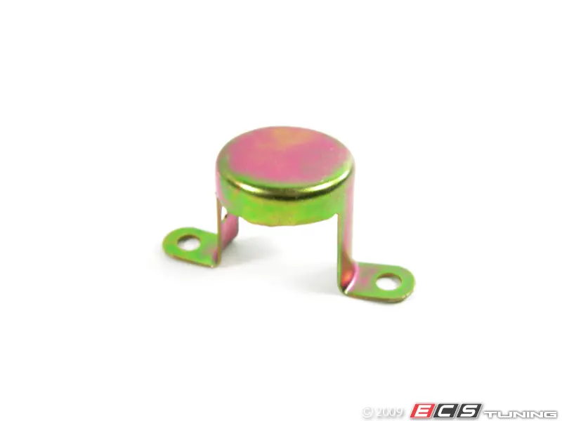
Judging by its photo, it is screwed together with the sensor and presses the connector. It's a strange decision, because apparently in order to remove the connector, you will need to unscrew the sensor. Otherwise, it will be very inconvenient to do it. Maybe that's why it was replaced with a rubber cap? These are just my guesses... but I have never seen him on cars, not even in a photo on the Internet. A strange detail, and given its inadequate price at $105, not needed at all, as for me! :)
So, we connect the speed sensor, close the connector with a rubber cap. We fasten the wire to the edge of the gearbox cover with a metal clip. By the way, ETK does not have it, but it is on almost all cars. Next, three plastic clamps on body studs under the trunk.

And two more clamps of the same type above the rear beam.

Wires to the fuel level sensor and the fuel pump are fixed with tape in a special groove on the body.

And the wiring must be installed BEFORE installing the tank. Because if they fall out when installing the tank, it will be very difficult to push them between the tank and the body. By the way, probably for the same reason, they were laid in my cabin and pressed with a cover under the seat.
The wiring goes into the cabin through a rubber sleeve. The connector for docking with the main wiring is fixed with another plastic clamp.

The wire for the fuel level sensor of the additional tank is pulled into the hole near the tank ventilation pipe and exits into the trunk.

There it is connected to the sensor of the additional tank and is attached with metal clips to this tank. In my case, there will be no additional tank. Yet. Therefore, the sensor will simply lie somewhere behind the trunk lining.

The last wire to the brake pad wear sensor is attached with three plastic clips to the right handbrake cable.

After the brakes are installed, this connector is fixed with a special clamp on the metal bracket of the protective cover of the brake disk. But it will be in another section of ETK, on brakes.
The rear part of the body wiring is installed.
I also installed ABS sensors, but about them separately.
So, everything is installed under the bottom, except for the gimbal. Also, the brake calipers have not yet been installed - they are in the process of restoration.
Next, according to the plan - the rear part and body wiring.Leave a comment:
-
Yes, I agree - even in appearance this grill does not inspire much confidence. But the goal of my project is to collect as many original options as possible. Therefore, I am more interested in this grille as a "collector's exhibit" and not as a practical engine protection.
By the way, I drove for seven years on a low suspension -60mm on our bad roads without any engine protection at all, and I never broke the lower engine pan.Leave a comment:
-
The factory skid plate or engine cover isn't worth the bother since it collects debris very effectively and provides about as much protection as a cope cage does for a tank in a modern war zone. Either get an aftermarket unit, or omit it entirely.Leave a comment:
Leave a comment: