Starting my M54B30 swap...

Collapse
X
 
  • Time
  • Show
Clear All
new posts
  • Elysian
    Mod Crazy
    • Apr 2010
    • 674

    #76
    Manuals for Megasquirt-3 (MS3) ECUs (1.5.x firmware) The manuals are split into three main sections : 1. Setting Up, 2. Hardware and 3. TunerStudio Reference. Manuals are available to download as PDFs or to view online page by page in your web-browser. 1. Setting Up This manual contains a QuickStart… Continue reading


    These. Just loaded firmware 1.0.2 onto it, also tested it in TunerStudio MS.

    Wasn't sure about this step:

    21) R37 and R38 are 'sense' resistors for the current limiting circuits on the injector drivers. Normally these should be installed. If, however, you prefer to do without the current limiting and want to make two spaces on the heatsink bar, then you can instead link out R37 and R38 by soldering a copper wire between the 2 holes in each. Ensure the link is flat to the board as you may need a component on the heat sink later on in the build.

    but I went ahead and installed R37 and R38 anyways. There was some other stuff I wasn't 100% on as well(with regards to my build), but I'll have to read those instructions again to figure out what it was.

    Comment

    • Elysian
      Mod Crazy
      • Apr 2010
      • 674

      #77
      26) Idle valves:
      The MS3 card has support for a 4 wire stepper idle valve built-in, just requiring 5 jumpers on the mainboard.
      When using the MS3X card in addition it is suggested that you install these jumper wires and use the standard 'FIDLE' components.
      If using 2 wire PWM idle without the MS3X card, you will need to upgrade the 'FIDLE' circuit on the V3.0 board. Note, the PWM Idle Valve circuit upgrade can also be used to drive other solenoids such as boost control.
      i)Stepper Idle Valve: If using a 4 wired idle valve (or using as two spare outputs) then solder wires from:
      a) JS0 to IAC1A
      b) JS1 to IAC1B
      c) JS2 to IAC2A
      d) JS3 to IAC2B
      e) Solder components Q4, Q20, R39 and D8 in place. Note, this gives you a programmable output that can drive a relay e.g. cooling fan on FIdle (Pin 30 of the db37)

      ii) PWM Idle Valve:
      Note! This is not required with the MS3X card - use one of the mid-current outputs on the MS3X card for you idle valve and fit the standard components Q4, Q20, R39, D8.
      2, 3 wired devices need a TIP122 (not supplied in kit) and mica insulation.
      a) Cut the legs of the TIP122 so they are half the length they were as new.
      b) Fit a piece of mica insulation under it and using plastic screws bolt it to the case or a space on the heatsink. Don't forget the mica.
      c) Solder a wire from the centre pin of Q4 to the left side of the TIP122.
      d) Solder a wire from the bottom pin of Q4 to the middle pin of the TIP122
      e) Get an IN4001 (you should have a spare from D2) and solder the stripped end of it into s12, this is below the TIP122 on the main board.
      Push it all the way in so the body sticks up in the air against the board.
      f) Solder a wire from the non-banded side of the diode to the centre pin of the TIP122.
      e) Solder a lead onto the copper wire that’s in position R43 to the right sided pin of the TIP122. (Ground for the TIP122 Idle driver)


      iii) No Idle Valve:
      a) Solder components Q4, Q20, R39 and D8 in place. Note, this gives you a programmable output that can drive a relay e.g. cooling fan relay on FIdle (Pin 30 of the db37)
      This stuff, I'm pretty clueless here.

      Comment

      • nando
        Moderator
        • Nov 2003
        • 34827

        #78
        Ill get back to you later, but with the ms3x you dont need to worry too much about that stuff. What you do need are the proper jumpers for the crank sensor, tach output, and a way to trigger the main relay.
        Build thread

        Bimmerlabs

        Comment

        • Elysian
          Mod Crazy
          • Apr 2010
          • 674

          #79
          Originally posted by nando
          Ill get back to you later, but with the ms3x you dont need to worry too much about that stuff. What you do need are the proper jumpers for the crank sensor, tach output, and a way to trigger the main relay.
          Is the main relay one of the relays attached to the harness on the left here? I need to pull out my E46 Bentley and get studying.


          I just pulled the harness off the M54, it was so easy; thanks BMW for making everything a quick disconnect connector

          Also got the MS3X today, it's now installed. Going to wait on fully buttoning it up obviously, looks like I still have some work to do.

          Comment

          • nando
            Moderator
            • Nov 2003
            • 34827

            #80
            Yes, its usually white. I have a circuit diagram that will work, i just need a pinout chart for the m54. The tach and crank sensor are easy - i think the m54 uses a vr crank and hall cam?
            Build thread

            Bimmerlabs

            Comment

            • Elysian
              Mod Crazy
              • Apr 2010
              • 674

              #81
              Originally posted by nando
              Yes, its usually white. I have a circuit diagram that will work, i just need a pinout chart for the m54. The tach and crank sensor are easy - i think the m54 uses a vr crank and hall cam?
              Looking through the Bentley it looks like it has a sensor per cam. Was just able to identify some stuff I hadn't been able to figure out as well, glad I cracked it open finally. I'm not sure how to figure out what types of sensors it uses though :(

              Looking through my PM's with hoveringuy, it's Hall crank.
              Last edited by Elysian; 09-06-2011, 05:47 PM.

              Comment

              • Elysian
                Mod Crazy
                • Apr 2010
                • 674

                #82
                Which forum is the best for MS3X stuff? I got on MSExtra forums and MSEFI forums, MSExtra seems kind of dead...

                Comment

                • hoveringuy
                  R3VLimited
                  • Dec 2005
                  • 2675

                  #83
                  Question: Are you going to wire the motor from scratch or just tap into the M54 harness?

                  I'm thinking about running MS on my M54, my approach would be to gut an old 413 and do a pin-to-pin connection so I can swap back and forth between ECUs. It would also leave all the relays in place and such.

                  Comment

                  • Elysian
                    Mod Crazy
                    • Apr 2010
                    • 674

                    #84
                    Originally posted by hoveringuy
                    Question: Are you going to wire the motor from scratch or just tap into the M54 harness?

                    I'm thinking about running MS on my M54, my approach would be to gut an old 413 and do a pin-to-pin connection so I can swap back and forth between ECUs. It would also leave all the relays in place and such.
                    I'm going to splice into the M54 harness. Don't have anything to go back and forth between besides the stock MS43, and I don't want to mess with that thing 
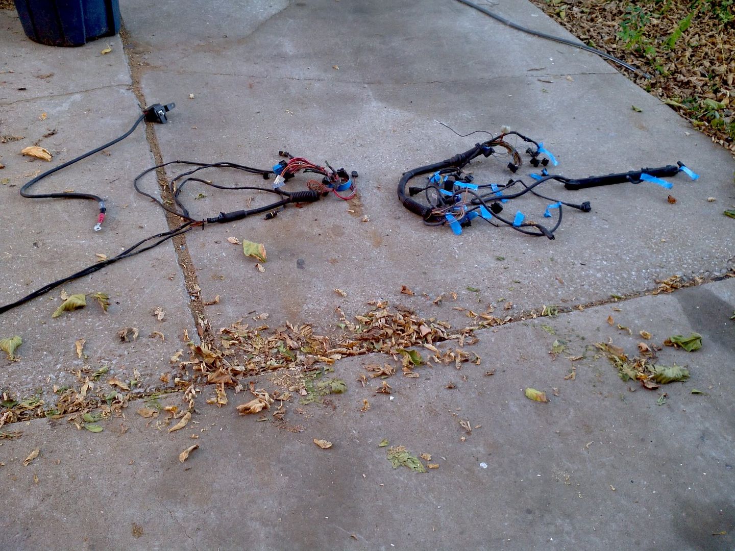
But I do want to have all the same connectors for easy reassembly.

                    Comment

                    • Elysian
                      Mod Crazy
                      • Apr 2010
                      • 674

                      #85
                      Got my Zionsville thermo in. Still waiting on the MS3X harness but I do have the main harness to work with for now.

                      Comment

                      • Elysian
                        Mod Crazy
                        • Apr 2010
                        • 674

                        #86
                        MS3X harness got here today. Can't seem to find the original harness for my coils :/

                        Comment

                        • Elysian
                          Mod Crazy
                          • Apr 2010
                          • 674

                          #87
                          Finally found the harness for my coils. I'm reading that someone doing an M50 swap ran 330ohm resistors on the signal wires for the stock COP, does anyone know if it's the same deal for the M54?

                          Comment

                          • Elysian
                            Mod Crazy
                            • Apr 2010
                            • 674

                            #88


                            Just found this guy, running a turbo 325xi, some good information in that thread. Been looking at his other threads as well. He seems to still be running the stock DME as well, makes sense because it controls so much crap on the E46.

                            Comment

                            • Elysian
                              Mod Crazy
                              • Apr 2010
                              • 674

                              #89


                              Bought these, gonna run all custom gauges when I put the new engine in. Still more to buy but for the price I couldn't say no.

                              Comment

                              • Elysian
                                Mod Crazy
                                • Apr 2010
                                • 674

                                #90
                                Contacted gurov and he told me about this:


                                Also gave me his MSQ file and a couple of others. Lots of great, very helpful information.

                                Comment

                                Working...